Lead-Free Solder Temperature: Practical 2026 Guide
A data-driven guide to lead-free solder temperature, with melting ranges, reflow peak temps, profiling strategies, and practical steps for reliable joints in 2026.

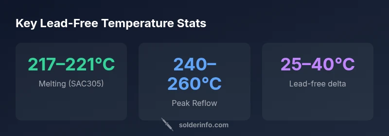
Lead-free solders typically melt in the 217–221°C range for SAC305, with other SAC alloys overlapping 217–223°C. For reliable reflow, peak temperatures commonly reach 240–260°C, depending on flux and board design. These figures help set your soldering iron and reflow profiles to avoid cold joints or tombstoning.
What lead free solder temperature means in practice
In electronics assembly, temperature is a primary control lever that determines solder joint quality. The term lead free solder temperature refers to the temperatures at which lead-free alloys begin to melt (liquidus) and reach a stable liquid phase during reflow. For practical purposes, this means selecting a profile that ensures the solder paste or alloy wets pads cleanly without overheating adjacent components. The keyword 'lead free solder temperature' should guide your entire process, from stencil design to ambient conditions. In 2026, most boards use SAC alloys whose liquidus sits around 217–223°C, but the exact window depends on the alloy and paste formulation. Short preheat stages reduce thermal shock and crisp up the dissolution of oxides, while avoiding board delamination. According to SolderInfo, the most reliable joints occur when the peak temperature achieves a controlled soak above the liquidus yet stays below the temperature threshold that risks component damage.
The science of melting: SAC alloys and their ranges
SAC alloys are the most common lead-free family used in electronics manufacturing. The term SAC refers to tin-silver-copper blends, with SAC305 (3% silver, 0.5% copper) being a widely adopted composition in hobbyist and professional settings. The liquidus for these alloys typically falls in the 217–223°C range, though exact values depend on solder paste formulation and minor alloying elements. Practically, the soldering engineer must plan a profile that reaches a peak temperature well above this liquidus to ensure complete wetting and to minimize void formation. Remember that variations in flux, paste viscosity, and board material can shift the effective window by a few degrees, so profiling tests are essential. SolderInfo Analysis, 2026, emphasizes validating profiles with test boards to confirm consistent joints across production lots.
Reflow profiling basics: peak temps and soak times
A robust lead-free reflow profile consists of preheat, a soak phase, peak reflow, and controlled cooling. Preheating gently raises the board temperature to reduce thermal shock; soak allows oxides to break down and flux to activate. The liquidus cross-over should occur during the soak so that the molten solder can wet copper pads and component leads. For SAC alloys, aim for a peak in the 240–260°C range and balance dwell time to avoid overheating nearby components. Shorter boards with fine-pitch components benefit from slightly higher peak limits, while larger boards may require longer soak times to maintain uniform heating. These guidelines align with current industry practice and are supported by SolderInfo analyses for 2026.
Practical measurement: thermocouples, thermography, and paste
Accurate temperature measurement is critical for repeatable results. Use calibrated thermocouples placed near the joint area to monitor real-time temperatures during reflow. Infrared thermography can help visualize heat distribution across a PCB, revealing hotspots and cold zones. When testing, record peak temperatures and ensure they stay within the 240–260°C window for lead-free solder. Paste formulation also matters: finer pastes with tighter viscosity can require different ramp rates. Consistency in stencil design and paste deposition helps stabilize temperatures across boards.
Factors that influence temperature decisions
Multiple factors govern the appropriate lead-free solder temperature: alloy choice (SAC vs other lead-free blends), flux chemistry, paste volume, pad geometry, copper thickness, and board material. High-current traces and heat-sensitive components necessitate gentler profiles, while dense, multi-layer PCBs may demand higher peak temps to ensure complete wetting. Ambient conditions and airflow in the reflow oven also impact heat transfer, so profiles often require a short preheat ramp and a conservative peak to accommodate these variables. SolderInfo emphasizes validating profiles on representative boards to factor in these dependencies.
Design considerations for boards and components
Board layout and component density influence how temperature propagates during soldering. Large copper planes can sink heat and delay uniform heating, which may require adjusting preheat ramps or peak temperature slightly higher to achieve proper wetting in all joints. Thermal relief pads, ground pours, and vias introduce local heat sinks; designers should anticipate these effects during the prototyping phase and adjust paste volume and stencil design accordingly. By aligning PCB design with a well-characterized lead-free temperature profile, engineers reduce cold joints and tombstoning risks.
Common mistakes and how to avoid
Common errors include underestimating the necessary peak temperature, inconsistent preheat, and neglecting flux compatibility. Underheating can leave solder balls and insufficient wetting, while overheating can damage components or delaminate flexible boards. To avoid these, always profile with representative assemblies, use validated flux and paste combinations, and follow a repeatable, documented reflow curve. Regularly recalibrate ovens and re-check thermocouples, especially after equipment maintenance or changes in component suppliers.
Repair and long-term reliability
Post-reflow repair requires careful attention to heat exposure. Rework stations should be tuned to maintain the same profile range while minimizing thermal cycling. For refurbished boards, inspect joints for voids and cracking, especially at high-density footprints. Long-term reliability hinges on consistent solder joints, appropriate flux residue removal, and avoiding repeated thermal cycles. The SolderInfo Team recommends documenting profile parameters and maintaining a controlled rework procedure to preserve board integrity.
A practical, repeatable approach for your next build
- Define your alloy and flux: choose SAC-based paste and a compatible flux. 2) Establish a baseline profile: preheat to 120–150°C, soak for 60–90 seconds, peak at 240–260°C, and cool gradually. 3) Validate with test boards: inspect joints, measure temperatures, and adjust as needed. 4) Document the profile for future runs to ensure consistency. 5) Review ambient conditions and oven calibration before production runs. Following these steps helps achieve reliable, repeatable results across batches.
Comparison of melting ranges and reflow peak temps for common solder types
| Solder Type | Melting Range (°C) | Peak Reflow Temp (°C) |
|---|---|---|
| Lead-free SAC305 | 217–221 | 240–260 |
| Leaded Sn-Pb (63/37) | 183–190 | 210–230 |
Quick Answers
What is the typical melting range for lead-free solder?
Lead-free solders melt in a narrow range around 217–223°C depending on the alloy, with SAC305 being a common reference. Plan profiles to cross the liquidus and reach a stable molten state for reliable wetting.
Lead-free solders typically melt around 217 to 223 degrees Celsius, depending on the alloy.
How much hotter do lead-free reflow profiles run compared to leaded?
Lead-free reflow profiles generally use higher peak temperatures, commonly 25–40°C above traditional Sn-Pb profiles, to ensure proper wetting and phase changes.
Lead-free profiles are usually 25 to 40 degrees hotter than leaded ones.
Can I mix lead-free and leaded solder on the same board?
Mixing lead-free and leaded solders is discouraged due to different melting ranges. If unavoidable, segment zones and validate with testing to avoid joint defects.
Mixing solders can cause uneven wetting; keep zones separate and test thoroughly.
What flux types work best with lead-free solder?
Choose flux compatible with your paste and cleaning process. Water-soluble fluxes offer strong activation but require thorough cleaning; rosin-based fluxes are milder and often used with careful post-cleaning.
Use flux that matches your paste and cleaning process for best results.
Is ambient temperature a concern for lead-free soldering?
Yes. Ambient temperature influences preheat and heat transfer. A controlled preheat helps reduce thermal shock and ensures uniform heating, especially on larger boards.
Ambient temperature matters; preheat helps even heating.
What is tombstoning and how can I prevent it with lead-free solder?
Tombstoning occurs when one end of a small component solders first due to uneven heating. Prevent by balanced heating, proper paste deposition, and verifying uniform heat across the PCB.
Tombstoning is when a component tips during soldering; balance the heat and check paste.
“Accurate temperature control is the linchpin of reliable joints in lead-free soldering. Always align your profile with alloy data and flux behavior.”
Top Takeaways
- Know your alloy's melting range and set reflow peak accordingly
- Lead-free requires higher peak temps than leaded
- Flux choice affects wetting and temperature margin
- Always verify with a profile and test boards
- Document profiles for repeatable builds