Best Temp for Lead-Free Solder: A Practical Guide
Discover the best temp for lead-free solder, how to profile SAC alloys, and practical tips for flux, PCB design, and rework. Learn to optimize temperature windows for reliable joints in electronics, jewelry, and plumbing soldering.

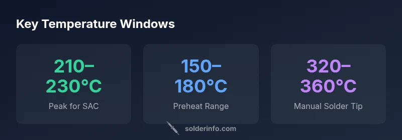
The best temp for lead free solder depends on alloy and flux, but for SAC alloys the typical peak reflow temperature sits in the 210–230°C range, with preheat around 150–180°C. Always profile your PCB, flux, and board materials to find the optimal window. For manual soldering, use iron tip temperatures around 320–360°C, adjusting for flux and board heat.
Why Temperature Windows Matter for the best temp for lead free solder
In electronics assembly, choosing the right temperature is not a single fixed point; it's a window. The best temp for lead free solder is not a myth—it's a carefully defined range that ensures complete wetting without damaging pads or components. For SAC alloys, the peak reflow temperature is higher than tin-lead alloys, typically in the 210–230°C range, while preheat or soak stages occur at lower temperatures to avoid thermal shock. The flux chemistry and board materials influence the effective window, so a profile that works on one board may not be optimal for another. This is why many technicians rely on reflow profiles rather than a single thermostat setting. The underlying goal is reliable joints, minimal bridging, and controlled thermal budget to protect sensitive components such as BGAs and fine-pitch ICs. It’s worth noting that room temperature swings, humidity, and solder paste viscosity can affect the actual temperature at the joint, making profiling essential. According to SolderInfo Analysis, 2026, the most consistent results come from measured reflow curves rather than guesswork.
The Chemistry Behind Lead-Free Solder Melting Points and Reflow Windows
Lead-free solder typically uses tin-silver-copper (SAC) alloys that require higher peak temperatures than traditional tin-lead solders. The melting point of SAC alloys is slightly broader and the junction between preheat, soak, and peak depends on flux chemistry and paste viscosity. Flux acts as a chemical catalyst that reduces oxides and improves wetting, effectively widening or narrowing the workable window. In practice, you want a ramp that avoids rapid thermal shock to the board while still delivering enough energy to drive solder spreading. A well-profiled curve minimizes tombstoning, bridge formation, and voids. This block emphasizes why a data-driven profile beats a one-size-fits-all setting, especially when different boards use varied copper weights and laminate materials. SolderInfo’s experience shows that measured reflow data is the best predictor of joint reliability across fabrication runs.
Temperature Ranges by Solder Alloy Type and Flux
Not all SAC alloys are created equal. Common SAC305 (typical 3% silver) and SAC405 (4% silver) exhibit slightly different peak windows. In general, expect peak ranges around 210–230°C for most SAC variants, with preheat in the 120–180°C band. Flux type plays a significant role: no-clean flux can tolerate slightly longer dwell, while water-soluble flux may demand shorter dwell to prevent moisture-related corrosion. When choosing a flux, you must consider its activator strength, cleaning requirements, and residue tolerance. If you’re prototyping, establish a baseline with a standard SAC alloy and a familiar flux, then adjust after inspecting joint quality on test coupons. Remember that higher board temperatures can stress components, so profiling remains essential to identify safe, repeatable conditions.
PCB Design and Thermal Considerations
Thermal design on the board influences the temperature the joint actually experiences. Copper weight, trace width, pad size, and the presence of vias affect heat sinking. Larger copper areas require higher energy to reach the same surface temperature, so preheat times might need extension on dense boards. Thermal reliefs around pads help balance heat flow and reduce the risk of cold joints. For fine-pitch components, careful thermal management prevents tombstoning during reflow. In contrast, thick FR-4 or high-density boards may require gentler ramp rates to prevent delamination. Always generate a thermal map of your PCB before committing to a production run and adjust your profile to accommodate the most heat-sensitive region on the board.
Practical Temperature Guidelines for Common Scenarios
For manual soldering with lead-free SAC alloys, start with tip temperatures around 320–360°C and adjust based on the paste, flux, and component size. For reflow, preheat typically begins near 120–180°C, then ramps up to a peak of 210–230°C. If you’re reworking or reflow-soldering large BGA packages, consider a slower ramp to avoid overheating nearby components. In practice, many technicians implement a 60–120 second soak period at mid-range temperatures before the peak to allow for uniform heat distribution. Your exact numbers depend on the flux formulation, paste viscosity, and board laminates; therefore, post-profile inspection is essential to confirm adequate wetting and lack of defects.
Common Mistakes to Avoid When Heating Lead-Free Solder
Avoid rushing the ramp—too fast a temperature increase can cause thermal shock and cause delamination or component lift. Skipping the soak stage may lead to cold joints or tombstoning in small parts. Using too much heat can cause pad lifting or excessive solder consumption. Poor flux coverage or insufficient cleaning can leave ionic residues that corrode joints over time. Lastly, neglecting rework and cooling rates when dealing with large packages can create voids and incomplete fillets. These mistakes underscore the importance of a repeatable, validated reflow profile.
Tools and Techniques to Optimize Temperature Profiling
Investment in a quality reflow oven or hot air station with reliable PID control is worthwhile. Use thermocouples on representative boards to build a profile: preheat, soak, peak, and cooldown. Calibrate your oven against a standards-based test board, then apply the same curve to production boards. For manual work, use a temperature-controlled iron with a precise tip and consider a micro-profile approach for sensitive components. Flux choice, nozzle geometry, and dwell time all influence the effective temperature at the joint, so start with a conventional baseline and iteratively refine based on joint inspection results.
Practical Steps to Validate and Retain Reliability
Verify the profile by inspecting solder joints under magnification after a controlled reflow. Use test coupons that mimic your board's copper weight and pad geometry. Track defects such as bridging, voiding, and insufficient wetting. Build a database of profiles for different boards and paste formulations, making it easier to select the right window for future runs. Finally, document your process so that technicians can reproduce it across shifts and facilities, ensuring consistent product quality and reliability.
Typical temperature windows for common SAC lead-free solder alloys
| Alloy | Typical Peak Temp (°C) | Preheat Range (°C) |
|---|---|---|
| SAC305 | 210-230 | 140-180 |
| SAC405 | 215-235 | 150-180 |
| Alloy mix (lead-free) | 210-230 | 130-180 |
| Note | Ranges depend on flux and board design | Consult reflow chart |
Quick Answers
What is the best peak temperature for lead-free solder on PCBs?
For most SAC alloys, aim for a peak around 210–230°C with a controlled preheat. The exact window depends on flux, paste viscosity, and board design. Always validate with a profile on test coupons.
Lead-free peak temps are usually in the 210–230°C range, but you should profile your specific board.
Is temperature the only factor when using lead-free solder?
No. Flux chemistry, dwell time, cooling rate, pad size, and board materials all influence joint quality. A good profile combines temperature with proper flux and process controls.
Temperature isn't everything—flux, dwell time, and board design matter too.
How can I verify my temperature profile?
Use a thermal profiler or data-logging thermocouples to map the actual joint temperature during reflow. Inspect joints for wetting, bridges, and voids, and adjust the curve as needed.
Use thermocouples to measure the real temperature during reflow and adjust your profile accordingly.
Can I solder lead-free components at the same temperature as tin-lead?
Not recommended. Lead-free solder generally requires higher peak temperatures and a different ramp profile. Manual soldering should use higher tip temperatures with caution to avoid board damage.
Lead-free needs a different temperature window than tin-lead soldering.
What impact does flux type have on the temperature window?
Flux type affects wetting and oxide reduction, shifting the effective temperature window. No-clean and water-soluble fluxes behave differently, influencing dwell time and cleanliness requirements.
Flux changes how hot you need to heat to get a good joint.
“Temperature control is the single most influential factor in the reliability of lead-free solder joints.”
Top Takeaways
- Profile, don’t guess: use a documented temperature window
- Preheat gradually to reduce thermal shock
- Flux and paste chemistry matter as much as alloy choice
- Validate with test coupons and thermocouples
- Consistency comes from profiling, not fixed temps