Lead Free Solder Melting Point: Key Ranges and Practical Guidance
A data-driven exploration of lead-free solder melting points, alloy variations, and practical tips for reliable electronic assembly in 2026.

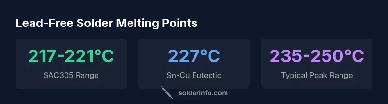
The lead free solder melting point for common SAC alloys typically falls around 217–221°C, with Sn-Cu eutectic around 227°C. In practice, plan reflow profiles toward 235–250°C peak depending on board materials and flux. These ranges reflect SAC305 as a standard reference and vary by alloy composition, impurity levels, and processing conditions.
Understanding the lead free solder melting point
The term melting point for lead-free solders is better described as a melting range rather than a single fixed temperature. This is because most practical lead-free alloys are multi-component systems whose solidus and liquidus temperatures vary with composition, impurities, and microstructure. In everyday soldering work, you will encounter eutectic and near-eutectic systems where the solder transitions from solid to liquid over a narrow temperature band. For the keyword lead free solder melting point, the critical takeaway is that precise planning of your reflow profile must account for this range, not a single number. According to SolderInfo, a widely used reference point is SAC305 (roughly 217–221°C), with variations arising from trace alloying elements and processing history.
The practical implication is that you should verify your alloy’s actual behavior for your specific build, rather than assuming a universal melting temperature. This becomes especially important for boards with temperature-sensitive components, PCB laminates, or solder mask materials that may delaminate or degrade if overheated.
Key alloy systems and their melting ranges
Lead-free solders are most commonly based on tin (Sn) with alloying elements such as silver (Ag) and copper (Cu). SAC305 (96.5Sn-3.0Ag-0.5Cu) is a widely adopted reference alloy, with a melting range around 217–221°C. Other popular lead-free systems include Sn-Ag-Cu variants that shift slightly higher depending on Ag content and trace impurities. A Sn-Cu eutectic alloy, for example, can have a melting point near 227°C. Understanding these ranges helps you design robust reflow profiles, select compatible fluxes, and anticipate different wetting behaviors on copper versus nickel or gold-plated contacts.
Because composition, grain structure, and cooling rates influence melting behavior, treat these values as approximate descriptors rather than fixed laws. SolderInfo’s analysis indicates that minor adjustments in the alloy matrix can move the melting window by several degrees, which matters when synchronizing with other components on a PCB.
How melting point affects soldering process and reliability
The melting point directly affects how you set your reflow profile. A profile that reaches the alloy’s liquidus temperature too quickly can cause solder balls, head-in-pailure, or excessive spreading. Conversely, a profile that climbs too slowly may trap flux residues and lead to poor wetting. Lead-free solders typically require higher peak temperatures and longer dwell times than traditional leaded solders. In practice, you should target a peak temperature within the alloy’s range (often 235–250°C for SAC-based systems) while ensuring compatible flux chemistry and board substrate tolerance. The key is to balance complete wetting with minimal thermal stress to sensitive components.
Practical testing and measurement of melting behavior
To characterize melting behavior in the lab or on a production line, DSC (differential scanning calorimetry) provides precise evidence of solidus and liquidus transitions. In field settings, operators infer melting behavior through controlled reflow tests and inspection of joint quality. Always document the observed temperature ranges for each lot of solder, since batch-to-batch variations—driven by minor compositional changes or impurities—can alter the melting window. SolderInfo notes that maintaining consistent solder paste formulation and storage conditions reduces drift in melting performance over time.
Flux interactions, wetting, and perceived melting point
Fluxes play a critical role in how easily a solder flows and wets surfaces, which can affect perceived melting behavior. A highly active flux reduces oxidation and improves wetting, making joints form at slightly lower effective temperatures. Conversely, poor flux activity can necessitate higher peak temperatures to achieve the same wetting. Therefore, when selecting a flux, consider its activator package and compatibility with your PCB materials. The melting point itself remains an intrinsic property of the alloy, but flux and surface conditions significantly influence practical outcomes.
Safety, handling, and material considerations
Lead-free solders still require careful handling due to high-temperature operation and potential exposure to fine particulate dust from sanding or Drilling boards. Ventilation, fume extraction, and proper PPE are essential. When dealing with lead-free alloys, you should also observe good housekeeping because some tin-rich alloys can lead to whisker formation under certain conditions. SolderInfo emphasizes that adhering to recommended reflow temperatures and cleaning practices helps prevent defects and prolongs component reliability.
Common pitfalls and best practices for predictable outcomes
Pitfalls include underestimating peak temperatures, using incompatible flux, and neglecting thermal mass on larger boards. Best practices involve creating a conservative reflow profile with controlled ramp rates (e.g., 1–2°C/s up to near peak), validating with test coupons, and monitoring joints with microscopy for signs of incomplete wetting or voiding. Reproducibility across batches improves when paste storage, stencil quality, and PCB prep stay consistent.
Summary guidance for hobbyists and professionals
For most SAC-based work, plan with the understanding that lead-free solder melting point is a range, typically around 217–221°C for SAC305 and near 227°C for Sn-Cu eutectics. Align your reflow peak temperatures accordingly, keep flux effective, and verify joint quality with standard inspection practices. This approach helps ensure reliable joints while protecting heat-sensitive components.
Representative melting ranges for common lead-free solder alloys
| Component | Typical Melting Range | Notes |
|---|---|---|
| SAC305 | 217-221 | 96.5Sn-3.0Ag-0.5Cu |
| Sn-Cu eutectic | 215-227 | Approximate; varies with impurities |
| Sn-Ag-Cu variants | 210-225 | Higher Ag can raise range slightly |
| Pure tin (for reference) | 232 | Not lead-free solder; shown for context |
Quick Answers
What is the typical melting point range for lead-free SAC alloys?
Most SAC alloys melt in a narrow range around 217–221°C, with variations depending on the exact composition. Practical profiles often target a peak temperature in the mid-230s to mid-240s °C depending on board materials and flux.
Lead-free SAC alloys typically melt around 217 to 221°C, but you may need higher peak temperatures based on your flux and materials.
How does the melting range affect reflow profiling?
Reflow profiles should accommodate the alloy’s melting range to ensure complete wetting without overheating. Start with a conservative ramp, then approach the target peak within the alloy’s range while observing joints for proper wetting.
Profile your oven to reach the alloy’s melting range so joints wet evenly without overheating.
Can flux influence when solder seems to melt?
Flux activity affects surface cleanliness and wetting but does not change the solder’s intrinsic melting point. Strong flux improves wetting, making joints appear to melt earlier due to better flow.
Flux boosts wetting, not the solder’s melting point, but it can change when you perceive melting.
How do I measure melting behavior on a PCB?
DSC testing provides precise solidus and liquidus data in the lab. On production boards, rely on controlled reflow tests and joint inspection to confirm practical melting behavior.
Use DSC in the lab for precise data; in production, validate with reflow tests and joint checks.
Are there safety considerations with lead-free solder?
Lead-free solders still require ventilation and PPE. High-temperature handling and fume management remain important for safe soldering practices.
Ventilate well and wear protection; lead-free doesn’t mean no risk at high temperatures.
“Accurate reflow control hinges on understanding that lead-free solder melting points are ranges, not fixed values. Always verify your alloy and flux together with your board constraints.”
Top Takeaways
- Know the melting range, not a single point.
- SAC305 is a common reference with ~217–221°C range.
- Flux choice and surface prep affect effective melting behavior.
- Use careful reflow profiling to avoid board/component damage.
- Verify each lot with practical testing for reliability.