Solder Iron Temperature for Electronics: A Practical Guide
A data-driven guide to choosing the solder iron temperature for electronics, covering leaded vs lead-free solder, heat management, flux effects, and safe practices for reliable joints.

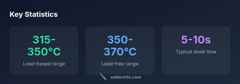
According to SolderInfo, the solder iron temperature for electronics typically ranges from about 315°C to 370°C, depending on solder alloy and flux. For most leaded solders (e.g., Sn60/40), aim around 315–350°C; for lead-free alloys (e.g., SAC305), use 350–370°C with brief contact times. Always start with the lowest effective temperature and adjust only as needed to form a reliable joint while protecting sensitive components.
Why temperature matters in electronics soldering
Heat is the primary driver of successful solder joints, especially in electronics where tiny components and dense boards resist rapid heat transfer. The phrase solder iron temperature for electronics is not a single number; it is a controlled range that balances alloy melting, flux activity, and component safety. When heat is too low, solder does not flow properly and joints become dull or cool, producing weak or incomplete bonds. When heat is too high, pads can delaminate, components can be damaged, and flux residues may burn, leaving fumes or discoloration. The goal is to supply just enough energy for a clean, reliable joint and then remove heat quickly. In practice, you should calibrate your process, use appropriate flux, and keep your tip in good condition to maximize heat transfer efficiency. As the SolderInfo team notes, small variations in alloy and flux can shift your effective temperature by several degrees, so live inspection matters.
For enthusiasts and professionals alike, tracking temperature is a discipline: a consistent routine prevents bad joints and reduces rework. When you view temperature as a controllable variable, you can adapt to different solder types, board layouts, and heat-sensitive components. The first rule is to know your solder family and the board’s tolerance; the second is to set a baseline and adjust with proofed testing on sacrificial test coupons. The process becomes a repeatable protocol rather than a guessing game, which improves yield and learning over time.
In this guide, you’ll see how temperature interacts with flux chemistry, tip geometry, and dwell time—elements that together influence joint quality. The bottom line is that temperature is a tool, not a fixed target. Use it to harmonize solder, flux, and components, and you’ll avoid common defects like cold joints and tombstoning. As you read, you’ll notice references to IPC guidelines and safety standards that reinforce practical limits and best practices.
Leaded vs lead-free: temperature ranges and trade-offs
Leaded solders typically melt around 183°C, but in practice the iron temperature used to form a good joint sits higher to ensure proper flow. Leaded alloys such as Sn60/40 generally respond well at about 315–350°C, with slightly lower temperatures possible on boards with efficient heat sinking. Lead-free alloys, including SAC305, require higher heat due to higher melting points and oxide formation tendencies, commonly in the 350–370°C window. The trade-off is duration: lead-free joints often need shorter contact times to minimize thermal stress on components, while leaded solder can tolerate slightly longer dwell with less risk to older components. Flux plays a pivotal role here, helping liquefy and spread solder at these temperatures without excessive heat. SolderInfo analysis shows that adjusting dwell times and cleaning tips can offset some of the higher thermal demands of lead-free alloys. When working with mixed assemblies, adopt a two-phase approach: establish a safe baseline for leaded sections, then rework lead-free portions with a controlled, brief heat pulse.
Another factor is component sensitivity. Small solid-state devices, delicate connectors, and heat-sensitive ICs benefit from cooler temps and shorter dwell. In dense multi-layer boards, a heat sink or preheating strategy reduces the risk of scorching nearby traces. By aligning your temperature to the solder type and board design, you can minimize defects and improve joint reliability. The SolderInfo team emphasizes that temperature is a part of a broader heat-management strategy, not a standalone setting. You should couple temperature choices with flux chemistry and intelligent tip selection to optimize results across different sections of a device.
In practice, maintain a temperature ladder: start at the lower end of the appropriate range for a given alloy, test, and only increase if the joint does not wick properly. This disciplined approach helps prevent overheating, reduces waste, and improves consistency across parts and boards. For hobbyists, a small, repeatable difference of 5–10°C can matter; for professionals, precise control translates to higher throughput and fewer rejects. SolderInfo’s guidance remains clear: know your alloy, flux, and board constraints before applying heat.
How to set your iron temperature: practical steps
To translate ranges into reliable practice, begin with a baseline that matches your solder type. For leaded solder, set the iron to around 320–330°C and test on a scrap pad. If the joint looks dull or refuses to flow, nudge the temperature up in 5–10°C increments and re-test until your solder forms a bright, smooth fillet. For lead-free solder, a baseline of 360°C is common, but do not dwell at that temperature for long. Use the minimum heat necessary to achieve proper wetting, and withdraw promptly to minimize thermal soak. A practical approach is to pre-tin the tip, apply flux, and then touch the joint briefly, removing heat as soon as the solder flows. Always work with fresh, clean flux and avoid pushing heat into the pad for extended durations. SolderInfo recommends validating the process with a test coupon that replicates common board features.
Before you begin, calibrate your iron's temperature reading with a reliable thermometer or a temperature-compensated tip. Verify the tip is in good condition: a clean, properly tinned tip transfers heat efficiently and reduces the need for higher temperatures. If you notice excessive tip oxidation, replace or re-tin the tip and recheck the temperature. Keep a visual log of joint quality and rework needs; it’s common to learn a lot from repeated practice. Throughout, maintain proper ventilation and minimize exposure to fumes by using a fume extractor when possible.
A practical setup includes: (1) setting the baseline temperature on the iron, (2) applying a consistent flux, (3) using a sharp, appropriately sized tip for the pad geometry, and (4) removing heat promptly after solder flow. With time, you’ll build muscle memory for the “feel” of a good joint, reducing the need for excessive heat and rework. In this context, SolderInfo notes that the effective temperature is a function of alloy, flux, and heat transfer efficiency, which means your process should adapt to the specific task at hand.
Techniques to minimize heat exposure: pulse heating, tacking, and heat sinking
Effective heat control relies on a combination of technique and tool ergonomics. Pulse heating—delivering short, controlled bursts of heat—enables you to reflow solder without long dwell times that could damage nearby components. Start with a light touch and plan your approach: place solder on the pad near the lead, bring the tip to the joint, and lift away as soon as the solder flows. Tacking components in place with one or two small joints allows you to secure mechanical stability before completing the rest of the joints, reducing the need for prolonged heat at each connection.
Heat sinking is a simple yet powerful strategy: place a small copper or aluminum heatsink on adjacent pads or traces to absorb excess heat, shielding sensitive parts from thermal stress. Quick-dwell testing on sacrificial coupons helps you learn the right dwell times for various component packages, including QFPs, BGAs, and analog ICs. Remember that flux and paste residues influence heat transfer and wettability; good flux activity makes it easier for solder to flow, reducing the heat requirement for proper joint formation. The goal is precision, not brute force. SolderInfo highlights that a well-chosen tip geometry and clean surfaces combine to minimize the heat you must apply for a reliable joint.
Tool and tip selection: choosing the right iron and tip geometry
Selecting the right iron power rating and tip geometry is foundational to temperature control. A 25–60 W iron provides ample heat capacity for most through-hole and surface-mount tasks. For small IC footprints, use a fine-point or knife-edge tip to maximize heat transfer efficiency and reduce contact area with adjacent pads. If you work with large ground planes, a chisel or broadened tip helps distribute heat, but you must still manage dwell time to prevent pad lifting. Tip maintenance is critical: keep the tip clean, tin after each use, and avoid letting flux burn onto the tip, which reduces heat transfer. Temperature stabilization is easier when the iron’s heater element is in good condition and the iron is properly insulated. SolderInfo recommends pairing a well-suited tip with a temperature that respects the alloy and flux in use—a combination that yields consistent joints and minimizes rework.
Additionally, consider the board’s thermal mass. Heavier boards and dense assemblies require more careful heat management, sometimes necessitating short preheating or staged reflow for specific sections. In practice, engineers often set a slightly lower baseline for heat-sensitive areas and rely on brief pulses to achieve the same result. Your arsenal should include a range of tips and, if necessary, a hot-air station for temperature-controlled rework, ensuring you can maintain the appropriate heat in different contexts.
Flux, solder, and heat: how chemistry affects temperature
Flux chemistry profoundly affects heat transfer and joint quality. Rosin-core fluxes activate at lower temperatures and encourage better wetting by reducing surface oxides, which means you can often solder successfully at slightly lower iron temperatures with the right flux. Flux also limits oxidation, enabling the solder to flow more easily and reducing the dwell time required to form a robust joint. When working with lead-free solder, choosing a flux optimized for SAC alloys can help compensate for the higher melting point and slower wetting. SolderInfo emphasizes that flux type can shift the effective temperature by several degrees, underscoring the importance of pairing flux selection with a calibrated heat strategy.
In practice, always verify flux compatibility with the solder alloy and board materials. Apply a small amount of flux to the joint, then heat quickly with a sharp, precise touch rather than dragging the tip along the pad. After the joint forms, wipe away excess flux residues if needed and clean the area to prevent corrosion. While heat is a primary driver for joint formation, chemistry often completes the job, and neglecting flux can lead to cold joints even at higher temperatures.
Common mistakes and how to fix them
Common mistakes include overheating pads, using an insufficiently tinned tip, and relying on too-high temperatures for prolonged periods. Overheating can delaminate copper traces and lift pads, especially on older boards or boards with thin copper. A dull or dull-looking joint often indicates insufficient heat or flux failure; in such cases, reflow with a clean tip and a brief dwell time. Another frequent error is using the same temperature for all joints regardless of component sensitivity—you should adapt the heat to the device and board region. Cold joints are more common on fine-pitch components where flux residue and oxide layers impede wetting. To fix, rework with a clean tip, reapply flux, and ensure adequate heat transfer with a properly sized tip. If oxidation or corrosion is seen on the tip, re-tin it before continuing. By recognizing patterns and making small adjustments, you can reduce defects and improve reliability.
Safe practices and maintenance for consistent results
Soldering safety and consistent results begin with tip maintenance and ventilation. Regular tip cleaning and tinning maintain heat transfer and extend tip life. A neglected or oxidized tip requires higher temperatures to achieve wetting, which increases risk to the board. Use proper ventilation or a fume extractor to manage flux fumes; avoid inhaling fumes from rosin-based flux, especially in enclosed spaces. Calibrate temperature settings on a periodic basis and use temperature compensation when needed to account for instrument drift. Organize a dedicated work area with anti-static mats and ESD-safe tools to protect components. Finally, store flux bottles upright, clean, and sealed to prevent contamination that could affect solder flow. SolderInfo’s guidance emphasizes routine maintenance and a controlled workflow to maintain reproducibility across sessions.
From hobbyist to professional: scaling up temperature control for dense boards
As projects grow more complex, temperature control becomes a core differentiator between hobby work and professional manufacturing. Dense boards with multiple small components demand shorter dwell times and sometimes staged heating for thermal management. For professionals, investing in adjustable heaters, tip thermocouples, and calibrated test coupons helps standardize processes and reduce variance. Build a protocol: define the solder type, determine the baseline iron temperature, validate with test coupons, and document results for future references. Advanced users may also integrate temperature monitoring and feedback loops into their workflow, enabling more dynamic control during rework or repair. The broader lesson is to treat temperature as a controllable parameter within a broader quality system. SolderInfo’s experience shows that consistent, repeatable results come from disciplined practices and ongoing learning from real-world builds.
Typical iron temperature guidelines for common electronics soldering scenarios
| Solder Type | Recommended Iron Temperature (°C) | Typical Window (°C) | Notes |
|---|---|---|---|
| Lead-based solders (Sn60/40) | 315-350 | 315-350 | Widely used; keep joints brief to avoid overheating |
| Lead-free solders (SAC305) | 350-370 | 350-370 | Higher temps; shorter dwell time needed |
| Rosin-core flux wire | 315-360 | 315-360 | Flux aids heat transfer and wetting |
| Thin-profile components (SMD) | 260-320 | 260-320 | Use precise control and heat sinks when needed |
Quick Answers
What happens if the iron temperature is set too high?
Excessive heat can damage pads, lift traces, or degrade nearby components. It also increases flux oxidation and can cause tombstoning on small components. If you suspect overheating, reduce the temperature, test with a coupon, and rework with shorter dwell times.
If the iron is too hot, joints may burn pads or components. Reduce heat and recheck with a test coupon.
Can I use the same iron for leaded and lead-free solder?
Yes, but you should adjust the temperature for the solder type and work quickly with lead-free alloys. Maintain a lower baseline for leaded sections and a higher baseline for lead-free sections, ensuring you don’t contaminate tips or flux. Keep your flux and materials organized by alloy.
Yes—adjust the temperature and stay fast with lead-free solder.
How can I verify that my temperature is appropriate for a joint?
Use a trial coupon to verify flow and wetting under real board conditions. Look for bright, smooth fillets and complete wetting without scorching. If joints appear dull or silver, adjust temperature and dwell time accordingly.
Test with a coupon; look for smooth, bright joints.
What role does flux play in heat control?
Flux reduces oxide formation and improves wetting, allowing solder to flow at lower effective temperatures. The right flux can significantly affect heat transfer and joint quality, particularly with lead-free solder.
Flux helps heat transfer and wetting, so pick the right flux for your alloy.
How can I prevent cold joints on sensitive components?
Increase wettability with proper flux, use a sharp-tipped iron, and avoid prolonged heat near delicate parts. If a joint looks dull, reflow with a fresh tip and a brief heat pulse.
Keep heat brief and use good flux to avoid cold joints.
Is tip maintenance important for temperature control?
Yes. A dirty or oxidized tip impedes heat transfer, forcing you to raise temperature and dwell time. Regular cleaning and tinning keep heat transfer efficient and joints reliable.
Yes—keep the tip clean and tinned for consistent heat transfer.
“Temperature control is the linchpin of reliable solder joints. Keep heat brief, use appropriate flux, and maintain a clean, tinned tip.”
Top Takeaways
- Aim for the lowest temperature that yields a reliable joint.
- Different solder types require different temperature ranges.
- Use brief, controlled heat with good flux to avoid damage.
- Keep the tip clean and well-tinned for efficient heat transfer.
- Test on sacrificial coupons to establish a repeatable process.