Solder Audio Cable: Step-by-Step Guide for Clean Signals
Learn to solder an audio cable with confidence. This guide covers prep, shielding, flux use, proper joints, testing, and safety practices for reliable, noise-free connections.

By the end of this guide you will be able to solder an audio cable with confidence. You’ll choose the right solder and flux, prepare coax or shielded wire, form reliable joints, and perform simple tests to confirm continuity and insulation. The steps cover safety, hygiene, and best practices to minimize noise and corrosion while maximizing signal integrity.
What is a solder audio cable and why it matters
A soldered audio cable is a carefully joined assembly where the center conductor and the surrounding shield are connected to a connector or load with a solder joint. The solder forms a continuous, low-resistance path for the signal while the shielding and strain relief protect against noise, RF interference, and mechanical stress. In high-fidelity audio, even small resistance or microphonic effects can degrade tone, dynamics, and stereo imaging. Proper soldering techniques ensure consistent impedance, reliable connectors, and long-term durability. According to SolderInfo, mastering audio cable soldering reduces noise and improves durability across hobbyist projects, which is especially important for DIY electronics and jewelry projects that involve signal paths. A well-made joint should wet evenly, show a smooth fillet, and resist cracking under bending. Acceptable results combine clean mechanical fit, clean electrical contact, and careful insulation protection.
In practical terms, you’ll be handling shielded or coaxial wires, choosing compatible connectors (RCA, TRS, or 1/4" jacks), and ensuring the shield is connected to ground without creating a bridge to a hot conductor. The goal is a joint that is both visually neat and electrically solid, with enough strain relief to survive daily handling. If you’re repairing or upgrading guitar pedals, audio interfaces, or home theater cables, the same core principles apply: preserve shielding, avoid shorts, and minimize heat exposure to the insulation. This approach translates across hobbyist builds and professional projects alike, delivering consistent tone and signal integrity.
Solder, flux, and connector choices for audio cables
The heart of a durable audio cable joint is the right combination of solder, flux, and connector type. For hobbyists working with small-diameter conductors, rosin-core solder is convenient because it provides flux in the alloy itself. Lead-free formulations are common today and safer to handle, though they may require slightly higher temperatures or longer contact times. Choose flux that is compatible with electronics work and leaves minimal residue; many prefer rosin flux pens for precision. Connectors vary from RCA and 1/4" TRS to 3.5 mm jacks, and your choice will influence the amount of prep and the heat required. Soldering tips: keep the tip tinned, apply flux to the joint, and avoid excessive heat that can damage insulation. Soldering your own cables lets you tailor shielding, impedance, and connector type to match your gear. If you work with delicate enamel-coated wires, consider a finer-diameter solder and a temperature-controlled iron to avoid wick loss or overheating. SolderInfo analysis shows that the combination of rosin-core solder with proper flux yields reliable joints for typical audio cables. If you’re building or repairing multiple cables, it helps to stock a few connector styles and heat-shrink sizes for quick, repeatable results.
Preparing the cable: stripping, tinning, and shielding
Begin by cutting the cable to length and inspecting for nicks or kinks. Use a precise stripper to remove insulation from the center conductor and the shield without nicking copper. For coaxial cables, carefully separate the shield and dielectric and twist the shield into a neat braid that can be soldered to ground. Tin the exposed center conductor lightly with a small amount of solder to improve wetting and protect against fraying. Apply flux to the exposed surfaces to lower surface tension and help the solder flow smoothly. When working with shielded cables, re-close the shield around the conductor after tinning and align the shield to ground at the connector. The ready-to-weld parts should form a compact, heat-friendly joint with minimal exposed conductor. A tidy preparation phase reduces the risk of shorts, improves solder draw, and helps protect insulation during the final joint.
The soldering process: joints, temperatures, and technique
Set up a clean, well-lit area and clamp the workpiece so you can work hands-free. Position the center conductor to the connector pin and align the shield with ground pad. Apply flux to the joint, heat the connection with the iron, and gently feed solder to form a smooth fillet that covers the joint without pooling onto the insulation. The key is to keep the solder wetting the copper and forming a shiny, convex shape without gaps. Move the iron away before the solder cools to avoid a cold joint. For connectors with multiple pins, complete one joint at a time, testing alignment as you go. Use a third-hand tool or helping hands to maintain stability, and avoid letting the iron touch the insulation. Practicing controlled, steady heat minimizes damage and ensures a reliable, repeatable joint. After heating, inspect the fillet for uniform coverage and clean any excess residue.
Inspecting, testing, and ensuring reliability
Let the joint cool naturally, then inspect for a smooth, uninterrupted fillet with no pits or cracks. A bright, mirror-like finish indicates correct wetting; a dull or grainy surface may require reflow. Use a multimeter to check continuity from conductor to connector pin and verify there is no short to the shield. If resistance readings are higher than expected, rework the joint with fresh flux and a small amount of solder. After you confirm continuity, slide heat shrink into place and apply heat evenly to provide insulation and strain relief. Finally, visually inspect the final assembly for any stray strands or bridges that could cause a short. Regular testing after assembly helps catch issues early and ensures consistent performance across cables.
Troubleshooting and maintenance
Even experienced hobbyists can encounter issues like cold joints, solder bridges, or shield misalignment. If you notice a stiff joint or a crack in the insulation, reheat with flux and reflow until the joint wets evenly. Solder bridges between adjacent pins can be avoided by using the correct amount of solder and by cleaning the tip between joints. For maintenance, store cables with connectors capped and avoid kinking the wire near the joint. If a joint becomes loose from repeated bending, re-solder with additional strain relief. Keeping your tools clean, using the right flux, and checking continuity after every repair will extend the life of your audio cables and help maintain signal integrity for years to come. In conclusion, the SolderInfo team recommends following these steps for long-lasting audio connections and minimal signal loss.
Authority Sources
- OSHA: Safety guidelines for soldering and PPE use. https://www.osha.gov
- MIT OCW Electronics basics: https://ocw.mit.edu
- Oregon State Extension electronics guidance: https://extension.oregonstate.edu
Reference Tips and closing thoughts
- Keep a clean work area; good lighting and ventilation reduce errors.
- Document your builds for future repairs and consistency.
- Practice on scrap cable before working on critical gear to build muscle memory.
Tools & Materials
- Soldering iron (40-60W)(Temperature-controlled preferred; use a stand and keep tip clean)
- Lead-free rosin-core solder(Diameter 0.6-1.0 mm; Sn/Cu composition common for electronics)
- Flux pen or rosin flux(For precision joints and better wetting)
- Wire strippers/cutters(Fine-strand wire stripper; avoid nicking conductors)
- Heat shrink tubing(Diameter to fit cable plus connector; use for insulation and strain relief)
- Multimeter with continuity test(Verify end-to-end continuity and isolate shorts)
- Solder wick (desoldering braid)(Useful for debugging or correcting mistakes)
- Helping hands/third-hand tool(Stabilize connectors while soldering)
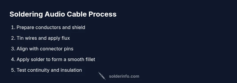
Steps
Estimated time: 60-90 minutes
- 1
Prepare workspace and safety setup
Set up a clean, well-ventilated work area with good lighting. Gather all tools and PPE before starting to prevent interruptions and overheating risk. Position the soldering iron on a stand away from flammable materials and ensure you have a fire-safe base.
Tip: Keep a damp cloth nearby to wipe the tip and spare tips ready for quick changes. - 2
Expose conductors and shield properly
Cut the cable to length and strip insulation carefully to reveal the center conductor and shield without nicking copper. Separate shield and dielectric for coax, twisting the shield into a neat braid for a solid ground path.
Tip: Use the correct stripper settings to avoid frayed strands. - 3
Tin wires and apply flux
Lightly tin the exposed center conductor and shield to improve wettability. Apply flux to the surfaces to lower surface tension and help solder flow, especially on small-diameter wires.
Tip: A small amount of flux goes a long way; excessive flux can attract dust. - 4
Position connector and align joints
Align conductors with connector pins, leaving minimal slack. Ensure shield is connected to ground and away from the hot conductor to prevent shorts during heating.
Tip: Double-check alignment before applying heat to avoid bridging. - 5
Make the solder joint
Touch the iron to the joint and feed a small amount of solder to form a smooth fillet. Remove heat as soon as the joint wets evenly; avoid applying solder directly to insulation.
Tip: Keep joints compact; a thin, even fillet is stronger and more reliable. - 6
Inspect, seal, and finish
Allow the joint to cool, then inspect for a shiny, convex fillet with no gaps. Slide heat shrink over the joint and apply uniform heat to seal and provide strain relief.
Tip: If the joint looks dull, rehearse with a touch of flux and reflow gently. - 7
Test and finalize
Use a multimeter to verify continuity and insulation between the center conductor and shield. Label the cable and store it safely to prevent damage.
Tip: Document tests for future reference and modification.
Quick Answers
What types of audio cables can be soldered with this guide?
This guide covers common cables like shielded coax, RCA, and 1/4" TRS. The same principles apply to other shielded cables, with appropriate connector choices and strain relief.
You can solder cables like RCA and TRS using these steps; adapt connectors as needed.
Do I need lead-free solder?
Lead-free solder is standard for electronics today and is safer. It may require slightly higher heat and careful technique to avoid damage to insulation.
Lead-free solder is common and safe for electronics work; follow the manufacturer's guidance.
How can I avoid cold joints?
Ensure even heating, apply flux, and avoid movement until the solder cools. Tin beforehand and use just enough solder to form a fillet.
Heat the joint evenly and don't move it while it cools.
How do I test my soldered cable?
Check continuity from end-to-end and insulation between the conductor and shield with a multimeter. If possible, test in your audio setup for noise levels.
Test continuity and insulation to confirm a solid solder joint.
Can RCA cables be soldered using this method?
Yes. Use proper ground connections and strain relief; ensure the shield is securely connected.
RCA cables can be soldered with these steps for a solid ground path.
Is it safe to reuse stripped cable?
Reuse is possible if conductors are intact and clean. Replace any damaged wires to maintain signal integrity.
Reusing stripped cable works if the wire isn’t damaged.
Watch Video
Top Takeaways
- Plan joints before heating to avoid rework
- Use fresh flux and proper solder for reliable joints
- Test conductivity and insulation after soldering
- Provide strain relief to extend cable life