Can You Solder Speaker Wire? A Practical DIY Guide
Learn how to solder speaker wire safely and reliably with this step-by-step guide from SolderInfo. Tools, techniques, and troubleshooting for strong audio connections.

By soldering speaker wire, you can create secure, low-resistance connections for DIY audio projects. The essential steps include stripping insulation cleanly, tinning wires, choosing the right solder and flux, and testing continuity before final enclosure. This guide shows a repeatable method suitable for beginners and pros alike. For best results, use lead-free rosin-core solder and heat-shrink insulation.
Soldering Speaker Wire: A Practical Foundation
Soldering speaker wire is a common technique in DIY audio projects, enabling consistent impedance and a reliable electrical path from amplifier outputs to speakers. According to SolderInfo Team, when done correctly, soldered joints can outperform crimp connections in terms of mechanical strength and long-term conductivity. Keep in mind that speaker wire comes in different gauges, and matching the gauge to your amplifier's load and the speaker input helps minimize resistance and audible loss. Stranded wires provide flexibility, while solid-core wires offer a tidier path in fixed installations. The goal is to create a clean, mechanically strong joint that conducts electricity with minimal resistance and without introducing cold joints or corrosion. A well-executed solder joint should be shiny, with a smooth fillet, and should appear secure to the touch. The steps outlined here apply whether you’re wiring bookshelf speakers, in-wall speakers, or car audio, but always tailor to your setup. With careful preparation, you can achieve a professional result that lasts for years. A well-executed joint also benefits from proper insulation and strain relief to withstand routine handling and vibration.
Tools, Safety, and Workspace Setup
Having the right tools reduces mistakes and increases safety. Gather a temperature-controlled soldering iron preferred 25-40W with a fine tip, rosin-core lead-free solder, wire strippers, heat-shrink tubing, and a multimeter for quick continuity tests. Ensure good ventilation to avoid fumes and wear eye protection. Secure the workpiece to prevent movement; a small vise or clamps helps. Keep water or a stand-by to quench any accidental slips; never touch the hot tip. Maintain clean, tangle-free cables and remove flammable materials from the area. The goal is a dedicated, well-lit space that minimizes thermal shock to components. Soldering speaker wire is straightforward but can be dangerous if you rush or work in a cluttered area. The SolderInfo team emphasizes a patient approach: check polarity before soldering and test each connection before you mount the assembly in its final enclosure. A clean workstation reduces the chance of stray solder bridging adjacent conductors.
Preparing the Wire: Stripping, Twist, and Gauge Match
Start by measuring the wire: typical speaker wire runs range from 16 AWG to 22 AWG. Use wire strippers to remove about 9-12 mm of insulation (slightly longer for thicker insulation to prevent frayed strands). Twist the exposed strands gently so they become a compact bundle. If using stranded wire, ensure all strands are evenly twisted to prevent random fraying during heating. For solid-core wire, ensure the conductor is fully supported and not kinking. The conductor should be bright and clean; oxidation impedes solder adhesion, so lightly abrade if needed and wipe away residue. The goal is a bright copper surface ready for tinning and a secure, uniform joint once soldered.
Flux, Solder, and Wire Alloys: Choosing Right Materials
Choose a rosin-core, lead-free solder in the 0.6-1.0 mm diameter range for most speaker-wire tasks. Rosin flux helps solder flow and prevents oxidation during heating. If your solder is core flux-less, apply a small amount of rosin flux with a flux pen to the prepared surface. Avoid acid flux for electronics; acid flux can corrode over time. For audio applications, a simple, no-clean flux is often sufficient, but flux residue is not harmful if left behind on non-corrosive surfaces. Select a solder alloy with a suitable melting point to reduce heat exposure to insulation; standard 60/40 or 63/37 tin-lead alloys are traditional, but many hobbyists now prefer lead-free variants like SAC305 or Sn100C. Note: In many regions, lead-containing solders are restricted; opt for lead-free alternatives. The aim is a strong, clean joint with minimal heat exposure that preserves insulation material and does not introduce contaminants.
The Soldering Process: Step-by-Step Execution
Initialize: Secure both wire ends and hold them side-by-side. Heat the joint area with the soldering iron; apply solder to the heated joint, not directly to the iron tip. Allow enough time for the solder to flow into the joint and form a small, smooth fillet. Remove heat and inspect the joint for a shiny, conical shape; a dull joint indicates a cold joint and should be reheated. If using heat shrink, slide the tubing over the joint before soldering; once cooled, apply heat to snug it around the joint. For best practice, ensure all strands are fully covered and there are no stray fibers. After soldering, trim any excess wire ends with a cutter. The joint should be mechanically solid and electrically continuous. Testing with a multimeter confirms continuity and correct polarity. Avoid overheating insulation, which can degrade plastics and reduce long-term reliability. If you notice a dull or grainy joint, reheat and reflow carefully while monitoring the temperature.
Insulation, Strain Relief, and Polarity
Slide heat-shrink tubing over the joint and use a heat source to apply a tight fit around the connection. Use proper strain relief near speaker terminals to prevent tugging on the solder joint. Be mindful of polarity: match positive to positive and negative to negative at each end to avoid phase reversals that degrade bass response and stereo imaging. For longer runs, consider double-wrapping with additional heat shrink or a cable wrap. Label each channel in multi-speaker setups to prevent confusion during maintenance. A robust insulation layer reduces friction, abrasion, and moisture ingress. The final goal is a durable, vibration-resistant connection that remains reliable under handling and transport.
Testing, Troubleshooting, and Common Issues
Check for continuity across the entire run; a hidden break in the wire may show as an open circuit or intermittent signal. Use a multimeter to verify resistance is low and consistent along the length. Listen for crackling or hiss that might indicate a poor joint or oxidation in the wire. If a joint looks dull or grainy, reheat and reflow until it shines; avoid scorching the insulation. For stereo systems, test both channels and verify sound reproduction with a known-good speaker. If you encounter a stubborn cold joint, consider re-stripping a small section and re-soldering. Always unplug equipment before testing to prevent electric shock or damage to gear. Regular checks after installation help ensure long-term reliability.
Advanced Tips for Durability and Longevity
Consider using heavier heat shrink on long runs to improve moisture resistance. For professional-grade audio installations, use soldered joints with proper strain relief rather than quick-connects where reliability matters most. In regions with high vibration, add ferrules or mechanical spacers near terminal posts to reduce stress on the solder. For long cables, calculate the resistance contribution of the wire gauge to avoid noticeable tone change, and opt for thicker gauge if necessary. Some technicians apply a small amount of silicone sealant around the solder joint for extra moisture protection in harsh environments; use sparingly and ensure it does not wick into the joint. With careful technique, soldered connections remain durable for decades when properly maintained.
Authority Sources
- OSHA (Occupational Safety and Health Administration): https://www.osha.gov
- NIST (National Institute of Standards and Technology): https://www.nist.gov
- MIT OpenCourseWare: https://ocw.mit.edu
Tools & Materials
- Soldering iron (25-40W, fine tip)(Set to a stable temperature; avoid excessive heat on insulation)
- Lead-free rosin-core solder (0.6-1.0 mm diameter)(Sn–Cu or SAC alloys are common; verify local lead restrictions)
- Solder flux or flux pen(Rosin flux helps flow; optional if no-clean solder is used)
- Wire strippers(Appropriate gauge range for speaker wire (16-22 AWG))
- Heat-shrink tubing (various sizes)(Pre-cut lengths to fit joints; slightly larger than wire diameter)
- Multimeter (continuity tester)(Useful for checking joints and resistance)
- Wire cutter(Clean cuts to prevent frayed ends)
- Clamps or helping hands(Stabilizes wires during heating)
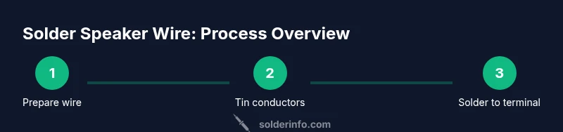
Steps
Estimated time: 20-45 minutes
- 1
Set up workspace and verify safety
Arrange tools, ventilate area, and wear eye protection. Clamp the speaker wire ends to prevent movement. Confirm you have all materials within reach and set the iron to a stable temperature to avoid overheating insulation.
Tip: Keep a damp cloth handy to wipe excess flux and cool the tip between joints. - 2
Prepare the wire ends
Use wire strippers to remove insulation from both conductors, exposing about 9-12 mm of copper. Twist strands gently to form a neat bundle and prevent fraying when heated.
Tip: If the insulation is particularly thick, remove a slightly longer section, but avoid nicking the copper strands. - 3
Tin the exposed conductors
Apply a small amount of solder to the exposed wire while heating with the iron. The goal is a thin, even coating on each conductor, which helps it flow into the joint later.
Tip: Do not melt too much solder; avoid globules that could prevent a clean joint. - 4
Join to the terminal or connector
Place the tinned wire against the terminal pad or connector lead. Heat the joint evenly and feed solder until the joint is fully filled with a smooth fillet. Remove heat and allow to cool without movement.
Tip: If using heat shrink, slide tubing over the joint before soldering, then shrink after it cools. - 5
Insulate and secure the joint
Slide heat-shrink tubing over the joint and apply heat evenly to form a tight seal. Add a short piece of tubing for extra strain relief if the run will be tugged or flexed.
Tip: Ensure no exposed copper remains after shrinking; gaps can cause shorts. - 6
Test connections
Use a multimeter to verify continuity and correct polarity. If you hear crackles or see resistance drift, rework the joint promptly.
Tip: Test both channels in a known-good configuration before final installation.
Quick Answers
Is soldering necessary for speaker wire connections?
Not strictly. Many installations use crimp terminals or push-in connectors. However, soldering can improve conductivity, reduce resistance, and provide a more durable mechanical bond, especially in fixed installations or where vibration is a factor.
Soldering is not strictly required, but it offers better reliability and conductivity for speaker wires, especially in fixed setups.
What gauge wire should I use for typical speakers?
Most small to mid-size speakers use 16 to 22 AWG wire. Heavier gauges (lower numbers) reduce resistance over long runs; lighter gauges are acceptable for short runs. Match gauge to the distance and power demands of your system.
Typically, 16 to 22 AWG works well; use thicker wire for longer runs.
Can I solder to banana plugs or binding posts?
Yes. Strip and tin the wire, then solder the conductor to the banana plug or binding post with the plug designed to take wire. Follow the manufacturer’s instructions to avoid overheating the connector.
You can solder directly to banana plugs or binding posts following their instructions.
Is lead-free solder safe for audio equipment?
Lead-free solders are common and safer for home use. They require slightly higher temperatures to melt but work well for most hobbyist audio projects. Ensure good ventilation when heating any solder.
Lead-free solders are safe for audio work; just follow heating guidelines.
Do I need flux for speaker wire soldering?
Flux helps solder flow and prevents oxidation. For many lead-free solders, rosin-core provides flux, but a small amount of flux can improve results on oxidized surfaces.
Flux helps you get a cleaner, stronger joint; use if surfaces look oxidized.
How can I verify the joint after soldering?
Use a continuity test with a multimeter and listen for consistent audio signal during a test playback. Look for a shiny, smooth joint and ensure there are no cold joints or shorts.
Check continuity with a multimeter and test playback to confirm solid joints.
Watch Video
Top Takeaways
- Prepare wire and tools before starting
- Tin conductors to ensure clean joints
- Use heat shrink for durable insulation
- Check polarity to avoid phase issues
- Test continuity and resistance after soldering