How to Solder XLR Cable: A Complete Tutorial
Learn how to solder an XLR cable with confidence. This guide covers tools, techniques, safety, and testing to deliver reliable microphone and audio connections.

You will learn how to solder an XLR cable end-to-end, including stripping wires, tinning, shielding, and connecting to the connector pins. This quick guide covers essential safety, recommended tools, and a reliable technique to minimize buzz and dropout. By following these steps, you’ll achieve a durable, professional audio connection.
What is an XLR Cable and Why Soldering Matters
An XLR cable is a balanced audio line designed to minimize noise and hum in microphone and line-level connections. When you assemble or repair one, knowing how to solder xlr cable properly ensures the signal remains clean and free of buzz. The skill combines conductor preparation, a solid solder joint, and a reliable shield connection. For DIY enthusiasts and professionals, mastering this task reduces downtime and yields durable cables that withstand regular use on stage or in the studio.
According to SolderInfo, clean execution matters as much as the right materials. A well-executed solder joint features a short, shiny fillet, minimal heat exposure to insulation, and a shield that makes solid contact with the connector shell. If you rush or overheat, you risk cold joints, intermittent contact, or brittle insulation. As you proceed, keep in mind that XLR pins carry both signal and ground, and the shield should be bonded to the connector housing to maintain noise rejection. This section lays out practical steps, common pitfalls, and a mental checklist you’ll use each time you work with XLR cables.
Safety and Prep: Set Up for Success
Soldering XLR cables requires attention to personal safety and workspace conditions. Work in a well-ventilated area and wear eye protection as solder can flicker under heat. Use a fume extractor if possible, and keep a temperature-controlled soldering iron set to a moderate temperature to avoid melting insulation or damaging the conductor. Static-free benches, a third-hand tool for stability, and a clean, organized workspace reduce mistakes and speed up the process. According to SolderInfo analysis, a stable workbench reduces accidental burns and improves joint reliability. Plan your steps in advance, minimize movements, and keep a small spare parts bin for quick replacements if a conductor breaks.
Tools, Materials, and Cable Preparation
Before you begin, gather essential tools and materials tailored for XLR cable work. A temperature-controlled soldering iron with a fine tip, rosin-core lead-free solder, and flux are must-haves. You’ll also need shielded XLR cable, heat shrink tubing in several diameters, wire strippers, side cutters, a helping hand or third-hand tool, multimeter for testing continuity, and desoldering braid as a backup. Prepare the cable by cutting to length, removing the outer jacket, and untwisting the shield so the individual conductors remain intact. Coil the shield back and reserve a short section for shielding the connector shell. This preparation minimizes stray strands and ensures a clean joint when you solder.
Soldering xlr cable reliably hinges on using the right materials. Rosin-core flux helps the solder flow into joints, while lead-free solder reduces health and environmental concerns. Keep a small amount of flux on the conductor before tinning to create a smooth, conductive surface. Heat management is critical: limit heat exposure to each conductor to avoid insulation damage and ensure the shield remains intact for noise rejection.
Understanding XLR Pinouts and Shield Ground
XLR connectors follow a standard pinout: Pin 1 is ground, Pin 2 is hot (positive), and Pin 3 is cold (negative). Some cables carry a fourth shield conductor that should be bonded to the connector shell and, when possible, tied to chassis ground at the source or destination. Whether you’re working with a male or female connector, maintain the same pinout mapping on each end of the cable to preserve phase and balance. Always verify the connector housing is grounded and that the shield is continuous along the cable length. If you encounter a mismatch in pin numbering, consult the manufacturer’s documentation for the specific connector family you’re using and adjust accordingly.
The Soldering Process: Core Techniques
Soldering an XLR cable requires precise technique. Begin by stripping the outer jacket and exposing a clean length of each conductor. Tin the wires lightly to prepare them for a strong joint. Align each conductor with its corresponding pin on the XLR connector and apply a small amount of flux to improve solder flow. Heat each pin area briefly and feed the solder into the joint rather than onto the iron tip to ensure a clean fillet. Avoid overheating the insulation, which can degrade the cable’s performance. When connecting the shield, fold the shield strands back and anchor them to the connector shell if the design allows. Allow the joint to cool naturally for a few seconds before moving the assembly. Precision and patience reduce the risk of cold joints and shorts, yielding a robust audio cable.
Finishing Touches: Insulation, Strain Relief, and Testing
After soldering, cover each joint with heat-shrink tubing to provide insulation and mechanical protection. Use a heat gun or carefully applied heat to shrink the tubing without overheating the copper. Slide a larger piece of heat shrink over the entire connector area to provide strain relief and reduce cable movement at the solder joints. Inspect each joint visually for a smooth fillet with no cold joints or bridges between conductors. Test the cable with a multimeter for continuity and a simple audio test with a known-good microphone or device to ensure the signal is clean and the shield is effective. This verification helps catch subtle faults before field use.
Troubleshooting Common Issues
If you hear hum, buzz, or crackling, recheck the solder joints for cold joints, bridges, or insufficient tinning. A poor shield connection will manifest as noise pickup regardless of your ground management. Reflow suspect joints with a clean tip and fresh solder, ensuring you don’t apply heat for too long. If continuity tests fail, re-examine pin alignment and ensure conductor insulation isn’t nicked or exposed to moisture. Finally, ensure strain relief is intact; excessive movement at joints can degrade the connection over time.
Practice Scenarios and Quick Tips
Practice on scrap lengths of shielded audio cable before committing to a final build. Focus on three core ideas: clean joints, proper shielding, and reliable strain relief. Build several practice cables with different connector genders to become familiar with both ends of the assembly. Keep a small practice kit ready so you can iterate on technique without wasting production parts. As you gain experience, you’ll reduce cycle time without sacrificing quality.
Tools & Materials
- temperature-controlled soldering iron(Fine-tipped iron (0.5–1.0 mm) preferred)
- rosin-core lead-free solder(Sn99.3-Cd0.7 or similar; 0.8–1.0 mm diameter)
- flux (rosin-based)(Pen or paste form)
- shielded XLR cable(Balanced, multi-conductor cable)
- heat shrink tubing(Assorted diameters for joints and shield)
- wire strippers(4–6 mm stripped length)
- desoldering braid(For clearing bridged joints)
- helping hands / third hand tool(Stabilizes the connector during soldering)
- multimeter(Continuity and resistance checks)
- flush-cutters(Trim conductors neatly)
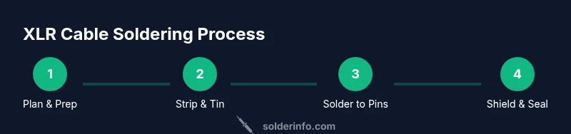
Steps
Estimated time: 45-60 minutes
- 1
Plan and verify cable and connector
Review the connector type and pinout for the XLR you’re using. Confirm you have the correct gender and the expected conductor count. This planning minimizes mis-wiring and saves rework later.
Tip: Double-check the pinout on both ends before cutting or stripping the cable. - 2
Set up a safe work area
Arrange your tools within easy reach. Use a clamp or helping hands to hold the connector steady while soldering. Ensure good ventilation to avoid solder fume buildup.
Tip: Secure the connector so it cannot move during soldering. - 3
Prepare the cable
Cut to length, then strip approximately 6–8 mm of the outer jacket. Gently twist and separate the shield from the inner conductors without nicking the insulation.
Tip: Keep the shield intact; a damaged shield increases noise pickup. - 4
Tin the conductors
Apply a light, even coat of solder to each conductor. Tinning reduces oxidation and makes it easier to form solid joints with the pins.
Tip: Do not over-tin; a thin layer is enough to improve flow. - 5
Tin the connector pins
Pre-tin the pins on the XLR connector to facilitate fast, reliable joints. This step ensures you have a good, conductive surface ready for the conductor wires.
Tip: Keep the iron on the pin only briefly to avoid heat damage to the connector housing. - 6
Solder the conductors to pins
One conductor at a time, apply flux and touch the pin with the iron while feeding solder into the joint. Maintain a clean, shiny fillet and avoid bridging adjacent pins.
Tip: Work methodically from pin 1 to pin 3; maintain consistent heat to prevent cold joints. - 7
Shield connection and final assembly
Fold the shield strands back and solder or clamp them to the connector shell as appropriate. Slide heat shrink over each joint and the shell, then shrink to form insulation and strain relief.
Tip: Check shield continuity to the shell after final assembly. - 8
Test, inspect, and finalize
Use a multimeter to verify continuity from pin to pin and shield to shell. Perform a short audio test with a known-good device to listen for hum or crackling. Rework any joints as needed.
Tip: Never skip the functional test; unseen faults can ruin performances.
Quick Answers
What tools do I need to solder an XLR cable?
Essential tools include a temperature-controlled soldering iron, rosin-core lead-free solder, flux, shielded XLR cable, heat shrink, wire strippers, a multimeter, and a helping hand. Optional items like desoldering braid can save time if you make a mistake.
Essential tools are a temperature-controlled iron, rosin-core solder, flux, shielded XLR cable, heat shrink, wire strippers, a multimeter, and a helping hand.
Which solder type should I use for XLR cables?
Use lead-free rosin-core solder for safer, cleaner joints. Rosin flux improves wetting and prevents oxidation during soldering. Avoid plain solder without flux on delicate cables.
Lead-free rosin-core solder with rosin flux is best for reliable XLR joints.
How do I test the XLR cable after soldering?
First perform a continuity check from each pin to the corresponding conductor. Then test the shield continuity to the connector shell. Finally, perform a functional audio test with a known-good mic or interface to confirm the signal is clean.
Check continuity on pins, shield, and perform an audio test to confirm signal quality.
What are common mistakes when soldering XLR cables?
Common mistakes include cold joints, overheating-insulation damage, shield not connected to shell, and poor strain relief. These can cause noise, weak connections, or failure in the field.
Watch for cold joints, overheating, and shield misconnection.
Is tinning necessary before soldering XLR pins?
Yes. Tinning the conductors and pins helps ensure an even, reliable joint and reduces the chance of oxidation during soldering. It also speeds up the soldering process.
Tin the wires and pins to improve solder flow and joint reliability.
Watch Video
Top Takeaways
- Plan, prep, and verify before soldering.
- Maintain proper heat control to avoid damage.
- Ensure shield and ground are solidly connected.
- Test continuity and signal integrity after assembly.