Circuit Board Solder Temperature: Guidelines for 2026
A data-driven guide to circuit board solder temperature, covering lead-free vs leaded alloys, measurement methods, and practical workflow for reliable PCB joints in 2026.

According to SolderInfo, circuit board solder temperature is a critical factor for joint reliability, component safety, and manufacturability. The ideal window depends on the solder alloy, flux chemistry, and board mass, but practical guidelines emphasize a defined process window to prevent cold joints, delamination, and tombstoning. This quick data point establishes the ranges and methods covered in detail below.
Why temperature matters in circuit board soldering
In electronics manufacturing, the circuit board solder temperature is not a single dial setting but a dynamic parameter that governs solder wetting, alloy flow, and thermal stress on both components and substrates. If the temperature is too low, solder may not properly wet copper pads, leading to cold joints and weak connections. If it is too high, heat-affected zones can damage epoxy resins, lift copper pads, or cause delamination of multilayer boards. SolderInfo analysis shows that maintaining a controlled process window—adjusted for alloy, flux chemistry, and board mass—reduces rework and improves first-pass yields. For DIY enthusiasts and professional assemblers alike, recognizing the circuit board solder temperature as an integral part of the workflow delivers more repeatable results in 2026.
Alloy differences and temperature windows
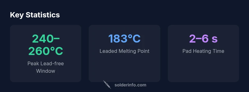
Solder temperature targets depend heavily on alloy choice. Classic Sn63/Pb37 (leaded) has a lower melting point around 183°C, while lead-free SnAgCu alloys melt higher, typically around 217–221°C. In practice, reflow peak temperatures for lead-free joints are often in the 240–260°C range, with ramp rates and soak profiles tuned to the board’s thermal mass. Flux chemistry also affects wetting and oxide remediation, meaning the same nominal temperature can translate to different joint outcomes on different boards. SolderInfo emphasizes a process window rather than a fixed value, since copper thickness, layer count, and component density shift the heat actually experienced by the joint.
How to measure and monitor temperature during soldering
Effective temperature control starts with proper measurement. Use thermocouples near the joint, calibrated infrared sensors, or validated hot-air stations to capture temperature data. Profile a representative board by recording preheat, peak temperature, and dwell times at each stage. For hand soldering, target a tip temperature aligned with the alloy and flux you’re using. A common starter range for lead-free work is 340–360°C on the iron tip, while leaded solders may perform well at slightly lower settings; adjust based on wetting results and pad condition. Flux chemistry, stencil quality, and board preheating all influence the final joint temperature, not just the iron tip. SolderInfo notes that practitioners who document settings and compare test coupons achieve more consistent results over time in 2026.
Practical guidelines for setting soldering iron temperature
When selecting a starting point, consider both alloy and flux. Lead-free alloys typically require higher tip temperatures than leaded ones—often by 20–40°C—so plan accordingly and verify with test coupons. For many hobbyists, beginning around 340–360°C for lead-free and 320–340°C for leaded is reasonable, with incremental adjustments based on how the solder wets pads and flows. Choose a precise, small-diameter tip to minimize heat transfer to adjacent pads, and keep flux activated and fresh. Maintain your iron tip in good condition to ensure consistent heat delivery. Document initial settings and update them as you accumulate test data from boards and components.
Thermal mass, preheating, and heat sinking considerations
Boards with large copper planes or thick multilayer stacks resist heat transfer, increasing the energy needed at the joint. Preheating the board in a controlled manner reduces thermal shock and warpage. Use heat sinks or copper pour attachments to protect sensitive components and adjacent traces. In dense areas, deliberate heat sinking helps prevent overheated vias or pads. For accurate and repeatable results, tailor your process to your board design and component mix, rather than applying a blanket temperature target. Profiling across boards of varying thicknesses remains a best practice in 2026.
SMT vs through-hole: Temperature profile differences
Surface-mount technology (SMT) relies on controlled reflow, where the entire board experiences a temperature ramp rather than a single localized heat event. Manual soldering of SMT pads should be brief to avoid tombstoning and bracketing of fine-pitch leads, whereas through-hole parts can tolerate longer heating but risk greater heat diffusion into the substrate. The takeaway is to customize the temperature profile to the joint geometry, flux, and solder alloy, validating the approach with representative test boards in 2026.
Rework scenarios and temperature management
Rework or removal of joints introduces thermal mass effects that can propagate heat to neighboring areas. Excessive heat can lift pads, peel solder mask, or cause delamination. Use heat barriers, ensure ventilation, and avoid prolonged exposure. In dense sections, consider alternative removal methods to minimize thermal load. Document rework profiles to establish a repeatable approach, and log temperature data to refine your baseline for future assemblies.
Common mistakes and how to avoid them
Errors include overheating, insufficient flux activation, and relying on a single temperature target without context. Always assess joint cleanliness, flux condition, and pad viability before soldering. Use appropriately sized tips and compatible flux for the chosen alloy, and avoid shortcuts with cleaning—residual flux can hinder wetting even at optimal temperatures. Establish a disciplined preheating routine and verify the temperature at the joint region, not only at the iron tip. In 2026, consistency and data-driven adjustments reduce rework and increase reliability, according to SolderInfo.
A practical workflow for consistent solder temperature control
Begin with a documented process window that specifies alloy, flux, board mass, and environmental conditions. Validate with pilot boards to establish a baseline, then scale with clear operator instructions. Implement periodic checks for peak temperature and dwell time, and maintain equipment calibration. A data log helps identify drift and enables iterative refinement of the temperature window. The SolderInfo methodology centers on reproducibility and auditable processes to sustain high yields in PCB manufacturing in 2026.
Temperature benchmarks for common solder types during PCB assembly
| Solder Type | Melting Point (approx) | Typical Reflow Peak (°C) | Notes |
|---|---|---|---|
| Leaded Sn63/Pb37 | 183 | 240–250 | Widely used in older boards; easier wetting |
| Lead-free SnAgCu | 217–221 | 240–260 | Common in modern manufacturing; must adjust flux |
| High-temp alloys | ~- | 250–270 | Specialty applications; verify compatibility |
| Flux-activated solder wire | - | - | Ensure flux matches alloy and cleaning steps |
| No-clean flux | - | - | Minimizes cleaning; watch residue impact |
Quick Answers
What is the ideal solder temperature for circuit boards?
There isn’t a universal temperature. The ideal value depends on the solder alloy, flux chemistry, and board mass. Use a documented process window and verify with test coupons.
There isn’t a single temperature—use a documented window and verify with tests.
How does lead-free solder temperature differ from leaded?
Lead-free alloys typically require higher peak temperatures than traditional leaded solders. Start with a higher tip temperature range and adjust based on wetting and pad condition.
Lead-free usually runs hotter; test and adjust for best wetting.
What tools help monitor solder temperature?
Thermocouples near the joint, infrared cameras, and calibrated hot-air stations are common tools. Profile test coupons to create a repeatable baseline.
Use thermocouples or infrared tools and profile test coupons.
Does flux affect temperature requirements?
Yes. Flux chemistry influences activation and oxide removal, which can change the effective joint temperature and wetting behavior. Always align flux with alloy and cleaning steps.
Flux changes how heat translates to wetting; pick it to match your alloy.
Can temperature variations damage components?
Yes. Excessive heat or uneven heating can damage sensitive components, pads, and the solder mask. Use proper heat sinking and avoid prolonged exposure.
Too much heat can hurt components and pads; manage heat carefully.
“Temperature control isn’t a single number; it’s a working window that changes with alloy, flux, and board design. Treating it scientifically reduces rework and improves yields.”
Top Takeaways
- Define a process window based on alloy, flux, and board mass
- Lead-free alloys generally need higher temperature than leaded counterparts
- Measure and profile joint temperatures, not just iron tip temperature
- Preheat and heat-sink to manage thermal mass and avoid warpage
- Document settings and build a repeatable, auditable workflow