What Temperature Solder Electronics: A Practical Guide
Learn the temperatures used in electronics soldering, how heat affects joints, and practical guidelines for leaded and lead-free solders. A practical SolderInfo guide.

Typical soldering temperatures for electronics fall in the 180–260°C range, depending on alloy and component sensitivity. Lead-free solders often require higher peak temperatures (around 240–260°C) with careful ramp rates and short contact times to avoid damage. Use temperature profiling, flux, and appropriate tip temperature to minimize solder joint defects.
What Temperature Solder Electronics Means for Beginners
According to SolderInfo, what temperature solder electronics requires hinges on alloy, board material, and component sensitivity. Temperature refers to the peak heat delivered to the joint, not ambient conditions. For most consumer electronics, a typical peak range for lead-free solders is about 240–260°C, while leaded solders can operate around 180–210°C. When people ask what temperature solder electronics requires, the answer depends on the alloy, the PCB materials, and the tolerance of sensitive components. The goal is to reach the solder’s melting point quickly and then remove the heat to quench the joint, allowing it to form without lasting damage. A controlled temperature profile minimizes bridge formation, tombstoning, and damage to copper traces. Flux and a clean iron tip dramatically influence effective temperature, so maintain consistent iron temperature and avoid drifts during a joint. The SolderInfo Team emphasizes practical temperature control as a core part of a reliable workflow.
How Temperature Affects Joint Quality
Heat is not the only factor; timing and method determine whether a joint is reliable. If the temperature is too low, solder fails to wet surfaces, causing cold joints and poor fillets. If it is too high or applied too long, components can overheat, leading to lifted pads, delamination, or melted plastic parts. A well-tuned temperature profile enables proper wetting, uniform fillet shape, and strong mechanical bonds. Preheating the board reduces thermal shock and spreads heat more evenly across dense boards. Flux chemistry also matters; an active flux lowers surface tension, allowing solder to flow smoothly at a given peak temperature. Remember that temperature is a tool, not a goal itself: the objective is a clean, reliable connection with minimal thermal stress. The right combination of solder alloy, flux, tip type, and controlled heat minimizes defects and improves long-term durability.
Leaded vs Lead-Free: Temperature Differences
Leaded solders typically melt at lower temperatures, allowing lower peak temperatures, while lead-free solders often require higher peaks to compensate for differences in wettability and melting behavior. The higher temperatures associated with lead-free alloys increase the risk of heat damage to sensitive components and boards if dwell times are not carefully controlled. Practitioners balance peak temperature with dwell, preheat, and flux to achieve reliable joints without compromising board integrity.
Temperature Profiling: Ramp, Soak, Peak, and Dwell
A good soldering practice follows a defined temperature profile: ramp up to a soak temperature, hold to improve fillet formation, peak to reach the solder’s melting point, and then dwell briefly to ensure complete bonding before cooling. Typical ramp rates are slow enough to avoid thermal shock (roughly 0.5–3°C/s, depending on board density). Soak times vary by board thickness and component density, but many technicians aim for short dwell at peak temperatures to minimize heat exposure. This disciplined approach reduces defects like bridging, icicles, and hot spots, and it helps protect heat-sensitive components.
Practical Guidelines for Common Electronics Tasks
- Surface-mount components (small resistors, capacitors): aim for a peak of 240–260°C with rapid, short contact.
- Through-hole components and connectors: allow a slightly lower peak and shorter dwell, typically 210–250°C depending on lead content and substrate.
- Dense PCBs and BGA/QFN devices: use preheat to 60–100°C to reduce thermal shock, followed by controlled peak exposure.
- Flux matters: use a compatible flux to improve wetting and allow lower effective temperatures.
- Tip selection and cleanliness: keep the iron tip clean and appropriately sized for the joint to maximize heat transfer and minimize dwell time.
Remember: these guidelines are starting points. Always adjust based on alloy, board material, and component sensitivity, and verify joints under magnification if possible.
Temperature guidelines for common electronics soldering tasks
| Aspect | Typical Range | Notes |
|---|---|---|
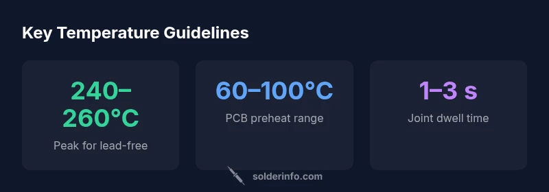
| Peak temperature (lead-free) | 240–260°C | Requires short dwell and fast quench |
| Iron tip temperature (hand soldering) | 290–320°C | Use flux and clean tip |
| Preheat range (PCB) | 60–100°C | Reduces thermal shock |
| Dwell time per joint | 1–3 s | Limit heat exposure to sensitive areas |
Quick Answers
What temperature should I use for lead-free soldering on electronics?
Lead-free solders typically require higher peak temps around 240–260°C; adjust to your alloy and board. Use short dwell and proper flux.
Lead-free soldering usually runs hotter; start near 240–260°C and tune for your materials.
Why does lead-free soldering demand higher temperatures than traditional tin-lead?
The melting point and wetting behavior differ between alloys; lead reduces surface tension, making lead-free alloys harder to wet.
Lead-free solders melt at higher temperatures and wet surfaces differently, so hotter heat is often needed.
How can I protect sensitive components from heat?
Use preheat, heat sinks, short dwell times, and appropriate flux; select a smaller tip for precision and minimize exposure.
Preheat the board and use heat sinks to keep sensitive parts safe.
What is tombstoning and how is temperature related?
Tombstoning happens when one leg of a small component heats faster than the other. Balance heating and use proper joint spacing.
Tombstoning occurs if heat isn’t balanced; ensure even heating of both legs.
What’s the difference between reflow and hand-soldering temperature profiles?
Reflow profiles use controlled ramp, soak, and peak steps across the board; hand-soldering relies on precise, brief heat with smaller dwell.
Reflow is a whole-board profile; hand-soldering is targeted and quicker.
“Temperature control is the backbone of reliable solder joints. With a proper profile, you minimize thermal stress and defects while achieving consistent wetting.”
Top Takeaways
- Follow a defined temperature profile, not a single number
- Lead-free solders typically run hotter than leaded varieties
- Flux and clean tips improve heat transfer and joint quality
- Preheat large boards to reduce thermal stress
- Adjust temperatures for component sensitivity and board layout