Solder XT90 Connectors: A Practical How-To Guide for RC
Learn to solder XT90 connectors safely for RC power leads with a step-by-step approach, tools, tips, and troubleshooting to ensure reliable, low-resistance joints.

By the end, you will be able to solder xt90 connectors cleanly and safely for RC power leads. This quick guide outlines essential prep, the correct solder and flux, heat-control techniques, and reliable strain relief. You’ll learn how to tin wires, terminate leads, inspect joints, and test continuity to ensure low resistance and strong mechanical connections. Expect to gather basic tools and work with lead-free solder while avoiding cold joints.
Overview and the role of XT90 connectors
According to SolderInfo, XT90 connectors are a popular choice for high-current RC power leads due to their compact size, robust polarity, and low contact resistance. When you solder xt90 connectors, you create reliable electrical paths from the battery to the ESC or power distribution system. This section explains why XT90s are favored in hobby builds, how their contact geometry supports steady current flow, and when you might choose alternatives like XT60 or Deans for different applications. It also discusses how solder joints compare to crimped connections and how that affects durability under vibration and temperature cycling. This knowledge helps hobbyists assess whether soldering is the best option for a given setup and which variant of XT90 to select (male vs. female) for your project.
Wire selection and connector compatibility
Selecting the right wire gauge and the correct XT90 variant is crucial. For most RC packs, 14-22 AWG silicone-insulated copper wire is common, with 18-20 AWG a safe middle ground for higher flexibility and adequate current handling. XT90 connectors come in male and female halves; ensure a proper mating pair and verify polarity to prevent reverse connections. The goal is to balance current capacity, heat generation, and strain relief, so you avoid oversized wires that don’t seat properly or undersized wires that overheat during sustained use. Consider the operating conditions (ambient temperature, vibration, and battery discharge rates) when choosing wire and connector combinations.
Workspace setup and safety considerations
Set up a clean, well-ventilated workspace with a heat-tolerant mat or board. Keep LiPo batteries away from the soldering area and never solder directly onto a live pack. Use a temperature-controlled soldering iron with a fine-point tip, plus a helping hand or third-hand tool to stabilize parts. Have safety gear handy—eye protection, good ventilation, and a fire-safe container for offcuts. A fan or fume extractor helps reduce exposure to flux fumes, and a fire extinguisher should be within easy reach for electrical fires. Establish a safe workflow that minimizes the risk of accidental battery puncture or shorting during assembly.
Prepping wires and XT90 terminals for termination
Before soldering, measure wire length and strip insulation precisely, exposing enough copper for a reliable tin but not so much that insulation is left exposed beyond the joint. Inspect XT90 terminals for oxidation or contamination and clean with isopropyl alcohol if needed. It’s helpful to pre-tin both the exposed copper and the connector tabs so the final joint flows smoothly and reduces the risk of cold joints. If using heat-shrink, slide sleeves onto wires before joining, so you can slide them into place after the solder joint is formed.
Tinning and forming a strong bond on XT90 joints
Tin the exposed copper wire ends with a small, even amount of solder to create a shiny, conical fillet. Apply a similar amount to the XT90 terminal surfaces to ensure complete wetting. Position the wire against the terminal and apply heat to the joint, not to the wire alone, until solder flows evenly across both surfaces. Avoid long heat exposure that could damage insulation or deform the connector body. Maintain steady, controlled heat and avoid creating bridges to adjacent conductors. Once cooled, inspect for a uniform fillet with no gaps or cold spots.
Insulation, strain relief, and final assembly
Slide heat-shrink sleeves into place to cover the solder joints and any exposed copper. Use a heat source to shrink evenly from the center outward, avoiding excessive heat that could melt insulation. For added durability, create a strain-relief knot or sleeve near the connector body and, if possible, tie the wires loosely into a small pigtail to distribute flexing forces. Check the completed assembly visually for uniform coverage and clean finish. After insulation, test the physical integrity by gently tugging on the wires to ensure the joint remains solid.
Testing, verification, and long-term maintenance
Connect a suitable load and use a multimeter to verify continuity and resistance across the joint. A clean, low-resistance reading indicates a good solder joint, while excessive resistance or intermittent readings signal cold joints, insulation damage, or poor wetting. Visually inspect the solder crown for shiny, uniform coverage and absence of gaps. Periodically re-check joints after vibration or temperature cycling, particularly in high-current RC applications, to prevent later failures.
Troubleshooting and common mistakes to avoid
Common issues include cold joints, overheating insulation, and poor wetting due to insufficient flux or uneven heat application. To avoid problems, ensure proper tinning, use fresh flux, and maintain consistent heat during soldering. Avoid letting the solder wick wick away from the joint or bridging to nearby conductors. If a joint looks dull or shows a gap, rework with fresh solder and a clean tip. Proper technique reduces rework and extends the life of XT90 connections.
Tools & Materials
- Soldering iron with fine-point tip(0.8–1.0 mm tip recommended for XT90 work)
- Lead-free solder (0.7–1.0 mm)(Sn99.3 Cu0.7 or equivalent)
- Rosin flux (no-clean)(Helps wetting; optional but recommended)
- XT90 connectors (male and female pairs)(Choose quality, gold-plated if available)
- Wire (18–22 AWG silicone insulated)(Common choice for RC power leads)
- Heat shrink tubing (2:1 or 3:1)(Pre-cut pieces for insulation)
- Wire strippers/cutters(Precise strip length)
- Helping hands / third-hand tool(Optional, helps steady parts)
- Soldering mat or fireproof work surface(Protects the bench)
- Multimeter(For continuity and resistance testing)
- Heat gun or lighter (for shrink tubing)(Use cautiously)
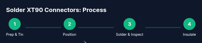
Steps
Estimated time: 45-60 minutes
- 1
Prepare workspace and safety
Set up a clean, ventilated area with a heat-tolerant mat. Ensure LiPo batteries are removed from the workspace and that you have a fire extinguisher nearby. Gather all tools and test equipment before starting to avoid mid-step interruptions.
Tip: Keep a metal tray handy for offcuts and avoid distractions near the battery area. - 2
Cut and strip wires to length
Measure the desired wire length and make clean straight cuts. Strip only the necessary insulation, exposing enough copper for a solid tin without leaving exposed strands that could short.
Tip: Use precise wire strippers to maintain uniform strip length across both leads. - 3
Pre-tin wires and terminals
Lightly tin the exposed copper ends and the XT90 terminal surfaces. The goal is a thin, shiny coating that wets quickly when joined. Avoid applying excess solder that could seep into the connector housing.
Tip: Tinning reduces the time needed to complete the final joint and improves wetting. - 4
Position wires against XT90 terminals
Place the stripped wire against the terminal, aligning polarity carefully. Use a helping hand or tweezers to keep alignment stable as you prepare to apply heat.
Tip: Double-check polarity before applying heat to avoid a reversed connection. - 5
Apply heat and form the joint
Apply the iron to the joint with consistent, moderate heat until solder flows and wets both surfaces. Do not linger with the iron on the insulation, and avoid bridging to nearby conductors.
Tip: Aim for a smooth fillet with a glossy finish; remove heat as soon as flow is achieved. - 6
Insulate and add strain relief
Slide heat shrink into place and apply heat evenly to shrink the sleeve around the joint. Add a strain-relief feature near the connector to reduce flexing stress on the joint.
Tip: Shrink from the center outward to avoid creating air pockets. - 7
Test and verify
Use a multimeter to check continuity and inspect visually for dull or cracked joints. Confirm the connector is mechanically secure and that there is no exposed copper or bleed paths.
Tip: Document your test results for future maintenance.
Quick Answers
What are XT90 connectors and why are they used in RC projects?
XT90 connectors are high-current, polarized power connectors commonly used in RC hobby projects. They provide a robust, compact interface between batteries and power systems, reducing resistance and preventing reverse polarity when correctly mated.
XT90 connectors are high-current power plugs used in RC hobbies to link batteries to the power system, chosen for their durability and polarity protection.
Should I solder XT90 connectors or crimp them?
Both methods work. Soldering provides a low-resistance joint suitable for custom wire lengths, while crimping offers speed and consistency for mass builds. For high-current, well-supported connections in RC setups, soldering with proper technique yields strong joints when insulation and strain relief are correctly applied.
You can solder for a strong, low-resistance connection, or crimp for speed and repeatability. Solder with care for high-current setups.
What wire gauge should I use with XT90 connectors?
Common practice is to use 18-20 AWG for moderate current RC applications and up to 14-16 AWG for higher current needs. The goal is to balance current capacity, heat generation, and flexibility without overloading the connector.
Typically 18 to 20 gauge wires work well for many RC setups; use thicker wire for higher current needs.
How can I prevent cold joints when soldering XT90 terminals?
Ensure proper tinning, clean surfaces, and consistent heat application. Use flux to improve wetting and avoid moving parts during solder flow. If a joint looks dull or cracked, rework with fresh solder.
Use clean surfaces, apply flux, and keep steady heat. Rework any dull or suspect joints.
Is it safe to solder near LiPo batteries?
Always keep LiPo packs away from the soldering area and never solder directly onto a live pack. Maintain a safe distance, use proper containment, and have a fire-safe plan in place.
No, solder away from LiPos. Keep safety protocols and a fire extinguisher ready.
How do I test a finished XT90 connection?
Use a multimeter to check continuity and resistance across the joint. Visually inspect the solder crown for a shiny, even finish and ensure there is no exposed copper. If readings are off, rework the joint.
Test continuity with a multimeter and inspect the joint for a clean, shiny finish.
Watch Video
Top Takeaways
- Tin wires and terminals for quick, reliable joints
- Maintain heat control to protect insulation and connectors
- Inspect joints visually and test electrically
- Use heat shrink and strain relief for durable connections