Reflow Solder: A Practical How-To Guide for Electronics
Learn how to perform reflow solder for surface-mount assemblies—from paste and flux to temperature profiles. A practical, step-by-step guide for ovens, hot plates, and quality checks.

By the end of this guide you will be able to perform reflow solder on surface-mount boards, from selecting solder paste and flux to choosing a reflow method and dialing in a safe temperature profile. You’ll compare convection ovens, hot plates, and dedicated reflow systems, learn placement best practices, and avoid common defects like bridging. According to SolderInfo, this approach reduces defects and yields reliable joints.
What is reflow solder and when to use it
Reflow solder is the process of melting solder paste to form reliable joints on surface-mount components. Unlike hand-soldering, which places individual wires or leads, reflow solder uses a printed stencil to deposit solder paste precisely where pads and leads meet. When components are placed, the entire board passes through a controlled temperature profile that melts the paste, allowing capillary action to form joints that cool into solid connections. Reflow is essential for high-density SMT assemblies, small geometries, and boards with many tiny pads. For hobbyists, reflow enables consistent results across multiple boards and reduces thermal stress by using an optimized ramp rate. According to SolderInfo, following a defined profile improves repeatability and reduces defects like shorts and cold joints. This article focuses on the practical steps you’ll need to reflow solder effectively.
Equipment and process overview
A successful reflow process starts with the right hardware and preparation. You need solder paste formulated for lead-free or leaded alloys depending on your project, flux to improve wetting, a stencil and scraper or paste syringe for paste application, and a heat source capable of a controlled ramp. Common options include a convection reflow oven, a hot air rework station, or a purpose-built reflow oven. Preparation also includes inspecting boards for soldermask integrity, ensuring components are correctly oriented, and checking for tombstoning or misalignment before heating. The goal is uniform heat transfer across the board to avoid overheating small features while ensuring all joints reach the melting temperature of the paste.
Solder paste selection and stencil considerations
Paste selection determines joint quality. Choose a paste with the correct alloy (lead-free or leaded) and viscosity for your stencil. A good rule is to match aperture size to pad size and use a stencil that minimizes bridging while ensuring enough paste for each joint. The stencil should be clean and properly aligned to prevent skewed deposits. After printing, allow the paste to heat uniformly during the preheat phase; this minimizes expansion of paste as it warms. Solder paste expiration and temperature stability are important; always store paste per the manufacturer’s guidance and discard after the stated shelf life.
Flux types and how to apply them
Flux improves solderability and corrosion resistance. Rosin-based flux is common for electronics, but active fluxes are available for heavy copper or oxidized surfaces. Apply flux thinly, focusing on pads and vias. If using vacuum-based placement, apply flux via a pen or flux-cloaked syringe to avoid excessive wetting. During reflow, flux burns off and assists in clean joint formation. Remember to clean assemblies after reflow if your flux is not no-clean, to prevent residue buildup that may affect reliability.
Reflow methods: oven, hot plate, and rework station
Convection ovens provide uniform heat with a defined cooling ramp, ideal for boards with many packages. Hot plates can be used for small prototypes or single-board runs, but require careful balancing of temperature and board spacing to avoid scorching. Rework stations combine heat and controlled airflow for local heating, useful for components that are sensitive to board-wide heat. Each method has trade-offs in throughput, consistency, and cost, so choose based on your volume and tolerance for defects.
Temperature profiles and process control
A proper temperature profile consists of preheat, soak, peak reflow, and cooling segments. Ramp rates should be gradual to minimize thermal stress, with a soak phase that activates flux and removes volatiles. The peak temperature must be above the solder’s melting point but below the damage threshold of components and PCB substrates. Cooling should be controlled to prevent solder joints from developing voids or cracks. For reliable results, document and reproduce your profile, especially when switching paste formulations or board geometries. SolderInfo analysis shows that a stable ramp minimizes delamination and ensures consistent joint formation across boards.
Troubleshooting common defects during reflow
Bridge defects often occur when paste is too close on adjacent pads or when stencil alignment is off. Voids can form if exposure to flux gases is excessive or if paste temperature is too high during reflow. Solder balls may appear if there is excessive paste or movement at the moment of reflow. Cold joints occur when the paste doesn’t reach its melting temperature, perhaps due to insufficient peak temperature or poor contact. Use inspection tools like magnification and X-ray where appropriate to identify hidden bridges or insufficient wetting, then adjust paste deposition, stencil alignment, or ramp rate accordingly.
Safety and best practices
Always work in a well-ventilated area and follow safety guidelines for solder flux and fumes. Use PPE, such as safety glasses and heat-resistant gloves, and keep a fire extinguisher nearby. When handling hot boards, avoid touching hot metal surfaces and give assembled boards time to cool before handling. Store pastes and flux in cool, dry places and label containers clearly. Regularly calibrate your reflow equipment and maintain a clean workspace to prevent accidental contamination of joints.
Quality checks and post-reflow steps
After reflow, inspect each joint for proper wetting, fillet shape, and absence of bridging. A simple visual check is often insufficient; use a magnifier or microscope to verify tiny SMT joints. If you see defects, reflow may be required or you may need to rework individual joints using a rework station. Clean up residues if your flux demands it, and store your boards in a clean area to prevent corrosion or oxidation on exposed copper. Documentation of your reflow profile and troubleshooting tips helps with future builds.
Tools & Materials
- Solder paste (lead-free or leaded as specified)(Choose alloy compatible with components and board spec)
- Flux (rosin-based or no-clean)(Thin, even application to pads and vias)
- Stencil and squeegee or paste syringe(Precise deposition to pad geometry)
- Reflow oven, hot plate, or rework station(Must support controlled ramp and temperature)
- Magnification tool or loupe(For joint inspection after reflow)
- Lead-free or leaded tweezers and PCB holder(Safe handling of boards)
- Gloves and safety glasses(Personal protection during heating)
- Solder wick or desoldering braid(For corrective action)
- Thermocouple or temperature logger(To validate profile on large boards)
- Isopropyl alcohol and flux remover (if needed)(Post-cleaning)
- Ventilation hood or fume extractor(Make-up air and fumes handling)
Steps
Estimated time: 60-120 minutes
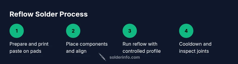
- 1
Prepare board and stencil
Inspect the board for soldermask integrity, clean surfaces, and align the stencil with pads. Ensure correct component orientation and remove any contaminants that might cause poor wetting. Verify that all pads are visible through the stencil apertures.
Tip: Double-check alignment under a loupe before depositing paste. - 2
Apply solder paste
Print or dispense a precise amount of solder paste onto each pad using a stable stencil or syringe. Maintain consistent pressure to prevent excessive paste height that can cause bridging.
Tip: Avoid air bubbles; keep stencil clean and free of dried paste. - 3
Place components
Position components accurately on the paste deposits using tweezers or a pick-and-place tool. Secure small bags or ICs with gentle tack to prevent movement during transfer.
Tip: Minimize handling to prevent displacement of paste. - 4
Preheat and soak
Preheat gradually to the soak phase to remove volatiles from flux and promote even heat distribution. This reduces thermal shock to components.
Tip: Use a stable ramp rate; sudden temperature jumps cause delamination. - 5
Run the reflow
Allow the board to pass through the reflow zone so paste melts and joints form. Maintain a smooth ramp and avoid rapid cooling to prevent cracks.
Tip: Keep a consistent cadence; don’t pause in the peak zone. - 6
Cooldown and inspect
Cool boards gradually to room temperature and inspect joints for proper fillets and wetting. Look for bridges, voids, or tombstoning, and document any anomalies.
Tip: Use magnification to confirm fine-pitch joints.
Quick Answers
What is reflow solder and how does it differ from hand soldering?
Reflow solder melts solder paste in a controlled environment to form joints for SMT components. Hand soldering uses a heat source to melt solder directly on each joint, which is slower and error-prone for dense boards.
Reflow solder uses paste and a controlled heat profile; hand soldering is more manual and slower for dense boards.
Can I reflow on a hot plate or only in a dedicated oven?
A hot plate can reflow small boards, but it’s harder to control the full board temperature profile and uniform heating. An oven or rework station gives more consistent results for multiple joints.
Yes, but ovens and dedicated reflow tools yield better consistency.
What paste should I use for lead-free electronics?
Choose a paste formulated for your alloy and board, commonly SAC305 or equivalent. Check paste viscosity, storage life, and compatibility with your stencil geometry.
Use lead-free SAC305 paste and follow storage guidelines.
What safety precautions are important during reflow?
Work in a ventilated area, wear eye protection, and use fume extraction. Keep flammable materials away from the oven, and monitor boards to prevent overheating.
Ventilate the area and wear protection; avoid overheating boards.
How do I prevent solder bridging?
Ensure correct stencil design and alignment, use properly sized apertures, and maintain paste volume appropriate for pad pairs. Adjust ramp rate and peak temperature if bridging persists.
Bridge issues come from stencil or paste; fix those and check the profile.
What are common reflow defects and how to fix them?
Common defects include bridges, voids, cold joints, and icings. Diagnose by inspecting solder joints, adjusting paste, stencil alignment, flux, and profile settings.
Bridges and voids usually mean paste or heat issues; adjust accordingly.
Watch Video
Top Takeaways
- Master paste preparation and stencil alignment.
- Choose the right reflow method for your volume.
- Dial in a repeatable temperature profile.
- Inspect joints with magnification for reliability.