Solder USB-C Connector: A Practical Step-by-Step Guide
Master soldering a USB-C connector with a detailed how-to. Learn preparation, heat control, flux usage, inspection, and troubleshooting for reliable, durable connections.

Learn to solder a USB-C connector safely and precisely with a clean workspace, a fine-tipped iron, proper flux, and magnification. This guide covers preparation, alignment, controlled heating, inspection, and troubleshooting to protect the connector, traces, and device. Practice on sacrificial test boards first, as recommended by SolderInfo.
Understanding USB-C Connector Soldering Challenges
Soldering a USB-C connector is a precision task that tests steadiness, control, and a methodical approach. USB-C connectors expose a dense array of pins, shielding, and high-speed signal traces, all packed into a tiny footprint. The vast majority of problems in hobby and professional work stem from heat mismanagement and misalignment. The SolderInfo team notes that the compact geometry makes it easy to bridge pins or lift copper traces if you rush the process. Success hinges on proper tooling, a clean surface, and a repeatable procedure that places the connector firmly before the first solder bead. As you work, keep in mind the connector’s orientation and the PCB’s pad layout. For a solder usb c connector, precision is essential, because even a slight tilt can misalign the daisy-chained pins and cause intermittent connectivity. The goal is a reliable, mechanically secure joint with minimal risk to nearby copper. Throughout this section you’ll hear how careful handling reduces rework and preserves signal integrity for USB-C interfaces.
Tools and Materials for USB-C Soldering
Having the right kit is half the battle when soldering a USB-C connector. The tiny pads and the shield’s metal shell demand a combination of finesse and robust materials. You’ll want a temperature-controlled, fine-tipped soldering iron (tip size around 0.3–0.5 mm) to reach the narrow pads without overheating neighboring traces. A quality magnifier or microscope helps you see each pin as you work. Flux matters: use a no-clean rosin core flux or a low-residue flux suitable for dense pin areas. Solder should be in a narrow diameter (0.3–0.5 mm) and either lead-free or leaded depending on your project’s requirements. Other essentials include flux pens, desoldering wick, isopropyl alcohol for cleaning, Kapton tape for masking, and anti-static equipment to protect sensitive components. Finally, practice boards aligned with your intended PCB footprint are invaluable for developing a repeatable technique before working on the final assembly. Remember to organize all items within reach to minimize time under heat exposure.
Preparing the Work Area and Connector
A clean, static-free work area is critical for successful USB-C soldering. Begin by grounding yourself and the work surface with an anti-static mat. Verify that the PCB footprint matches the USB-C connector’s pinout, and orient the connector so that the pin 1 indicator aligns with the PCB’s reference mark. Remove any previous solder or debris from the pad area using desoldering wick and neutral cleanser. Secure the connector with low-tack masking or a small clip so it doesn’t shift during soldering. Pre-apply a tiny amount of flux to the pads to improve wetting and reduce the heat needed to solder each pin. If you’re reworking, gently lift lifted pads with a fine tip or copper braid, then clean the surface before re-placing the connector. The goal is to create a stable, ready-to-wet surface so each pin wets evenly when soldering begins.
Pad Layout, Pin Mapping, and Grounding Considerations
USB-C connectors present a compact, symmetrical pad layout with multiple ground contacts and signal pins. The power and data pins must align precisely with the PCB pads to ensure reliable operation. Grounding is critical: the shield shell should be connected to ground to minimize EMI and help mechanical rigidity. Review the connector’s datasheet and your PCB silkscreen to confirm pin mapping. For solder usb c connector work, start by tacking the shield or two ground pads to establish a sturdy reference, then proceed with the high-density signal pins. Pay attention to anti-pad bridging: each pad is tiny, and a slight excess of solder can bridge adjacent pins. Using a bright light and magnification helps you identify potential bridges before they become a problem. If possible, use a micro-camera to check the underside of the connector after you place and tack it in position.
Soldering Strategy: Heat Management, Wetting, and Flux Practices
The key to a successful USB-C solder joint is controlling heat and ensuring proper wetting. Apply flux liberally enough to cover the pad surfaces, then use a clean, tip-tentative motion to wick solder onto each pad. Start with the ground/shield pads to anchor the connector mechanically, then move to the VBUS and signal pins. Use short, controlled heat pulses rather than a single prolonged exposure; this reduces the risk of delaminating the copper traces or overheating the connector. Tip maintenance matters: keep the soldering iron clean and tinned to maintain consistent heat transfer. If a pad resists, reflow nearby pads or re-tin the pad lightly rather than forcing the pin to wet. In some cases, pre-tinning large ground planes can help, but avoid creating large solder bridges that require later correction. Remember to keep the work at a steady pace to maintain tolerance on the connector’s delicate pins and to preserve signal integrity for high-speed pathways.
Common Problems and How to Avoid Them
Even experienced hobbyists encounter issues with USB-C connector soldering. Cold joints, bridged pins, lifted pads, or damaged traces can occur when heat is applied too long or unevenly. Bridge formation is especially common with slightly bent prongs or when pins are too close together. To prevent this, reflow each area in small stages, use flux to guide the solder, and apply just enough heat to wet the pad without spreading beyond. If a pad lifts or a trace becomes damaged, use a fine needle to re-etch the pad and re-tin it, then re-seat the connector. Always inspect with a magnifier after finishing each side so you can correct issues before moving on. For the best results with solder usb c connector work, practice on dummy boards to calibrate your technique and establish a reliable tempo for heating, flux, and pin alignment.
Inspection, Testing, and Rework
Post-solder inspection is essential. Examine each pin for full wetting, uniform fillets, and absence of bridges under magnification. Use a multimeter in continuity mode to confirm that power and ground paths are correct and that there is no unintended short between adjacent pins. If any joint looks suspect, perform targeted rework with flux and a warm iron or hot air station, focusing only on the affected pins. Desoldering wick helps remove excess solder from tight spaces, while a small-tipped iron permits precise correction. Keep the connector cool as you work to prevent solder from spreading to neighboring pins and pads. Finally, perform functional testing: power the board and check the USB-C port for proper detection and data transfer, verifying that data lines connect correctly and that the shield remains grounded.
Practical Scenarios: Through-Hole vs Surface-Mount USB-C Connectors
USB-C connectors come in different packages, including through-hole and surface-mount varieties. Through-hole variants offer mechanical stability on larger boards but require longer pins and more space. Surface-mount USB-C connectors minimize footprint and are common on compact devices, yet they demand higher precision because their pads are more closely spaced. When choosing between them, consider the application’s mechanical stresses, board thickness, and whether a jig or clamp is available to ensure alignment during soldering. In either case, the same principles apply: stable fixture, clean pads, precise heating, appropriate flux, and careful inspection. If you must work with a very tight footprint, sequence your soldering to anchor the shell first, then complete the pins in a logical order to minimize stress on the package.
Maintenance, Longevity, and Final Testing
After completing the USB-C soldering, conduct a final mechanical test to ensure the connector is firmly seated. A gentle flex test on the cable area helps identify weak joints or ground issues. Perform electrical tests to validate power delivery and data integrity; check for shorts by measuring resistance between adjacent pins and ground. If the connector passes these checks, consider applying a small amount of conformal coating in high-motion environments to protect exposed pins. Periodic inspection after field use can catch micro-movements or corrosion that develops over time. By following disciplined solder usb c connector practices, you’ll maximize joint reliability and device longevity.
Tools & Materials
- Temperature-controlled soldering iron (fine tip ~0.3-0.5 mm)(Aim for 300-350°C for lead-free solder; adjust to flux and connector rating)
- Fine-tine solder (0.3-0.5 mm)(Lead-free or leaded per project policy)
- No-clean rosin-core flux or low-residue flux(Improve wetting on dense USB-C pad arrays)
- Desoldering wick (braid) and desoldering pump(For correction of bridging or lifted pads)
- Magnification aid (loupe or stereo microscope, 3-5x)(Critical for tiny USB-C pins)
- Flux pen or syringe(Targeted flux application for tricky joints)
- Isopropyl alcohol (IPA) and lint-free wipes(Clean pads before and after soldering)
- Soldering mat and antistatic wrist strap(Protect device and components from static discharge)
- Solder wick vacuum or micro tweezers(For precise removal on small pads)
- PCB fixture or clamp(Keeps the connector from shifting during soldering)
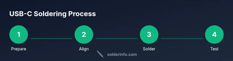
Steps
Estimated time: 60-90 minutes
- 1
Prepare work area
Set up on an anti-static mat. Ground yourself and ensure your PCB footprint matches the USB-C connector orientation. Pre-clean pads with IPA and inspect for any contaminants that could hinder wetting.
Tip: Keep tools within reach to minimize repositioning and heat exposure. - 2
Align and tack the connector
Place the USB-C connector so pin 1 aligns with the PCB reference mark. Lightly tack two ground pads to fix the connector without creating heat-bridges to nearby pins.
Tip: Use a small amount of flux on the ground pads to help this initial fix. - 3
Flux the pad array
Apply flux to all pad surfaces to improve wetting. Ensure every pad receives a thin, even coat so solder flows cleanly on each pin.
Tip: Avoid over-flux which can create solder pools and accidental bridges. - 4
Solder the shield/ground first
Heat the shield and ground pads briefly to form solid connections. Maintain perpendicular alignment to minimize bridging as you sweat the first joints.
Tip: Keep heat pulse short; excessive heat can lift pads. - 5
Solder high-density signal pins
Proceed pin by pin with a light touch, allowing each pin to wet with minimal heat. Pause between pins to avoid cumulative heating of the PCB layer.
Tip: Work from one side to the opposite to maintain control. - 6
Check for bridges and reflow as needed
Inspect under magnification for bridges between pins. If you see a bridge, reflow the involved pins, or wick away excess solder and re-tin the pads.
Tip: If you must rework, do not overheat adjacent pins; tiny drops can ruin nearby connections. - 7
Inspect and verify ground continuity
Test the shield and ground pins for a solid path to ground. A quick resistance check confirms there’s no unexpected short to VBUS or signal lines.
Tip: Use a datasheet pinout to confirm each ground contact is properly tied to ground. - 8
Final cleaning and inspection
Wipe away flux residues and inspect every solder joint with a magnifier. Look for dull or cracked joints that indicate poor wetting or heat stress.
Tip: Clean gently; avoid solvent soaking if delicate plastics are nearby. - 9
Functional test
Power the board and verify USB-C port operation: power delivery, data transfer, and cable recognition. Confirm mechanical stability with a gentle flex test.
Tip: If any failure occurs, repeat targeted rework on the suspicious joints.
Quick Answers
What temperature should you solder USB-C connectors at?
Use the solder manufacturer’s recommendations; for lead-free solder a typical range is around 300–350°C, with adjustments based on flux and connector tolerance. Avoid overheating to prevent pad lifting or shell damage.
Typically, aim for the manufacturer’s guidelines; commonly around 300 to 350 Celsius for lead-free solder, adjusted for flux and fit.
Do I need flux for surface-mount USB-C connectors?
Yes. Flux improves wetting on the dense pad array and reduces risk of cold joints. Use a no-clean flux or a low-residue flux suitable for tight spaces.
Yes, flux helps wetting for dense USB-C pads and reduces cold joints; use no-clean or low-residue flux.
Can I reuse flux after soldering?
Flux is generally not reused after application. Use fresh flux for new joints to ensure predictable wetting and to minimize solder splatter.
Flux isn’t reused; reapply fresh flux for each joint to ensure proper wetting.
What are common signs of a bad USB-C solder joint?
Common signs include a dull, cracked, or cracked-looking fillet; visible bridges between pins; and joints that don’t conduct. Inspect under magnification and test with a multimeter.
Look for dull or fractured joints, bridges, or non-conductive joints and test with a multimeter.
Is it safe to solder USB-C connectors on an energized board?
No. Always power down the board before soldering and discharge any static potential. Soldering on a live board risks component damage and injury.
No—power down the board and ensure it’s discharged before soldering.
What should I do if a pad lifts during soldering?
If a pad lifts, re-etch the trace lightly, apply fresh flux, and re-tin the pad before attempting to re-seat the connector. Consider a shield anchor or mechanical support to reduce stress.
If a pad lifts, fix the trace, re-tin, and re-seat the connector with mechanical support.
Watch Video
Top Takeaways
- Plan pin mapping before work begins.
- Control heat and use flux for reliable wetting.
- Inspect joints with magnification after soldering.
- Test electrical and mechanical integrity before final assembly.