Solder Size for PCB: A Practical Guide
A practical guide to selecting solder wire sizes for PCB work, covering common diameters, when to use each size, flux considerations, and best practices for reliable joints.

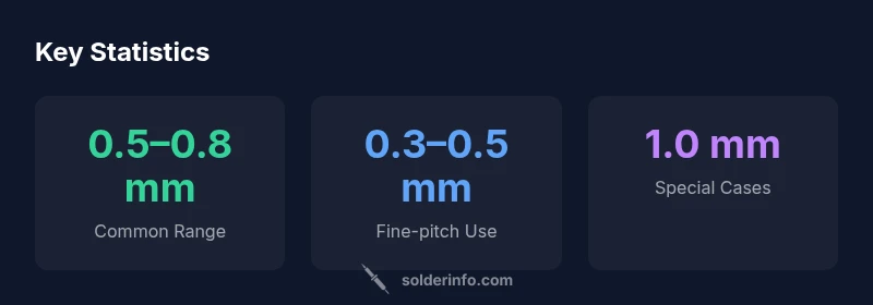
For PCB soldering, the most practical wire sizes are 0.5 mm to 0.8 mm. Beginners typically start with 0.8 mm for through-hole and larger pads, then move to 0.5 mm for fine-pitch components and dense boards. Avoid using wire that’s too thick on small pads, which can bridge; for easier flow, choose rosin-core solder and a clean flux.
Why solder size for pcb matters
Choosing the right solder size for pcb work is not a cosmetic preference; it determines heat transfer, pad integrity, and the longevity of joints. A wire that is too thick can bridge adjacent pads on a dense board, while a wire that is too thin may require more time and increase the risk of cold joints. In practice, electronics hobbyists and professionals alike rely on a few standard diameters—most commonly 0.5 mm, 0.8 mm, and occasionally 0.3 mm for fine-pitch work. The SolderInfo team notes that starting with a mid-range size and adjusting based on pad spacing, component density, and heat management leads to consistently reliable joints. Over the past year SolderInfo Analysis has seen a steady preference for 0.5–0.8 mm in typical PCB assemblies, with 0.3–0.5 mm reserved for very tight layouts.
Typical solder size for pcb wires and when to use them
Different PCB tasks call for different wire sizes. A 0.8 mm wire is forgiving and deposits solder quickly on larger pads and through-hole joints, reducing the risk of cold joints for beginners. For dense, fine-pitch components and small pads, a 0.5 mm wire offers better control and minimizes bridging. In some precision contexts, 0.3 mm wire is used, but it requires steadier hands and more practice. Lead-free and tin-lead variants behave similarly with respect to size, though melting temperatures and flow characteristics may differ slightly. Practically, assemble a small kit with 0.3 mm, 0.5 mm, and 0.8 mm diameters and choose based on pad width, lead thickness, and soldering iron tip size.
How to choose the right size for different components
The solder size for pcb should align with pad width, lead thickness, and feature density. For through-hole components with broad land patterns, 0.8 mm wire accelerates solder flow and reduces dwell time at high heat, helping protect nearby traces. For dense PCBs with tight spacing, 0.5 mm gives you finer control over joints and lowers the chance of bridging. Fine-pitch ICs may benefit from 0.3 mm wire when used with a sharp, well-cut tip and a steady hand. Always evaluate pad undercut, trace proximity, and the iron power setting before starting work.
Practical techniques for handling different wire sizes
When switching sizes, adjust your technique rather than forcing a single method. Keep the iron tip clean and tinned, and use flux to improve wetting. For 0.8 mm wire, feed a short length to the pad and let gravity guide it; avoid dragging a long tail across the board. For 0.5 mm, practice precise placement with a magnifier to prevent bridging on fine-pitch parts. With 0.3 mm wire, use a very small amount of fresh flux, a fine-tipped iron, and a patient hand to place the joint without overheating the pad.
Fine-pitch vs through-hole: wire size implications
Fine-pitch components demand more precise soldering control, so many technicians default to 0.3–0.5 mm wire, especially for QFPs and fine-pitch connectors. Through-hole joints tolerate 0.8 mm for rapid progress and robust heat transfer, but excessive heat on crowded boards can cause pad lifting. Always choose wire size based on pad pitch and the energy you apply with the iron; a proper match reduces rework and improves joint reliability.
Flux, solder alloys, and wire size compatibility
Flux type interacts with wire size to determine flow and cleanliness. Rosin-core flux is common for electronics because it helps solder to flow smoothly into small gaps, especially with 0.3–0.5 mm wire. Lead-free solders behave similarly, though their melting points are slightly higher and flow can be more sensitive to temperature control. When in doubt, pre-tin the iron tip and use a small amount of flux to prevent cold joints and improve overall joint quality.
Common mistakes and how to avoid them
A frequent error is using wire that is too large for the pad, which causes bridging and desoldering challenges. Another pitfall is overheating pads on high-density boards, which can delaminate layers. Conversely, too-small wire may require extended heating, leading to moisture uptake and dull joints. Practice with scrap boards, keep a clean surface, and always inspect joints under good lighting or with a loupe.
Maintenance and storage of solder wire
Store solder wire in a dry place, away from moisture and direct sunlight to minimize oxidation. Keep reels mounted and contained, and replace primers when corroded. If you use sealed containers, ensure air vents are unobstructed and cut only short lengths when needed to limit oxidation exposure. Rotate stock to ensure older wire is used first, and always reseal spools after use.
Safety and disposal considerations for solder wire sizes
Soldering generates fumes; work in a well-ventilated area and consider a fume extractor. Avoid touching lead or lead-free joints immediately after soldering; allow joints to cool before handling. Dispose of waste flux and contaminated materials according to local regulations, and never burn flux residues. Always maintain a tidy workspace to prevent accidental burns or injuries.
Guide to common solder wire sizes and uses
| Wire Size (mm) | Typical Use | Recommended For | Notes |
|---|---|---|---|
| 0.3 | Fine pitch SMDs | High-density boards | Challenging to handle |
| 0.5 | General electronics | Through-hole and medium-density PCBs | Common beginner size |
| 0.8 | General electronics | Compact boards and connectors | Widely available |
| 1.0 | Heavy wires, power joints | High-current joints | Rare in PCB work |
Quick Answers
What is the best wire size for beginners?
For beginners, 0.8 mm is forgiving on larger pads and through-hole joints. As skills grow, 0.5 mm becomes the go-to for tight spaces. Practice on scrap boards to build steady hand control.
For beginners, start with 0.8 mm. As you gain experience, move to 0.5 mm for denser boards.
Lead-free sizing differences
Lead-free solder generally uses the same wire sizes as traditional solders, with similar handling. Expect slightly different flow due to flux and alloy, but size choices depend on pad and lead geometry.
Lead-free solders use similar wire sizes; adjust more for flux and flow than diameter.
Wire size vs pad fit
If a joint occludes nearby pads or bridges traces, the wire is too thick. In dense areas, switch to a thinner diameter and control heat carefully.
If you see bridging, switch to a thinner wire and work slowly.
Thin wire and bridging
Thin wire can bridge if heat is excessive or technique is rushed. Use fresh flux, a steady hand, and short wire segments to prevent bridges.
Thin wire can bridge if you rush; take your time and use flux.
Solder wire storage
Store solder wire in a dry place to slow oxidation. Keep reels sealed when not in use and rotate stock to use older material first.
Keep it dry and rotate stock so older wire is used first.
Trimming solder wire
Trimming excess wire is fine but avoid long tails that can cause burns or accidental bridges. Use small snips and work with a clean bench.
Trim excess wire close to the joint with care.
“Choosing the right solder size is foundational to reliable PCB joints; consistent heat delivery and good wetting depend on matching pad and lead dimensions.”
Top Takeaways
- Start with 0.8 mm for through-hole joints
- Switch to 0.5 mm for fine-pitch work
- Avoid thick wire on small pads to prevent bridging
- Use rosin-core flux for better flow and cleanup
- Keep spare sizes handy: 0.3, 0.5, 0.8 mm