Solder vs Thermal Paste: A Practical Comparison for Electronics
Analytical comparison of solder versus thermal paste for heat transfer in electronics. Weigh reliability, workability, and best-use scenarios to guide hobbyists and professionals.

In most electronics, thermal paste is the standard thermal interface material, and solder is not a drop‑in substitute. Solder can offer higher conductivity in ideal, controlled conditions but introduces rigidity, rework challenges, and reliability risks from thermal stress. For DIY projects and general repairs, prioritize thermal paste and proper heatsinking; reserve solder-based substitutions for tightly controlled manufacturing contexts.
Context and Core Question: Solder instead of thermal paste in electronics
Choosing the right thermal interface between a heat source and a heatsink is a critical design decision that affects reliability, efficiency, and service life. The query solder instead of thermal paste surfaces frequently in niche discussions, but it is seldom appropriate for conventional devices. According to SolderInfo, the context, goals, and service life of the device strongly influence whether a substitution could ever be justified. This article analyzes contexts from hobby electronics to professional repair, weighing heat transfer, reworkability, and long-term reliability. In practice, this phrase highlights a risky substitution outside controlled manufacturing environments, and it should be treated with caution.
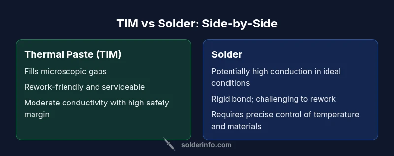
In most consumer devices, thermal paste is the standard because it fills microscopic gaps, accommodates surface irregularities, and allows for some compression during thermal cycling. Solder offers a different path: it can create a rigid, high-thermoconductivity bond that may reduce micro-gap issues but sacrifices reversibility and introduces stress and mismatch risks. The discussion that follows weighs these trade-offs without assuming a one-size-fits-all answer. SolderInfo’s cautious stance informs the analysis and helps readers understand when a substitution might make sense in theory but not in practice.
How heat transfer works at the TIM interface
A thermal interface material (TIM) fills the microscopic gaps between a heat source (such as a CPU or power transistor) and its heatsink. Because contact is never perfectly flat, air gaps form, which insulate and degrade heat flow. The TIM reduces thermal resistance by conforming to surface irregularities and by maintaining a consistent contact pressure across the interface. Material properties such as thermal conductivity, viscosity, and mechanical compliance govern performance. When evaluating substitutions, the key questions are: can the substitute fill gaps reliably, does it maintain contact pressure through thermal cycles, and is rework or removal feasible without damage? Solder generally offers higher potential conductivity than most TIMs, but it introduces rigidity and stress mismatches that can produce failure modes under repeated heating. This framework underpins the rest of the analysis, emphasizing practical constraints over theoretical advantages.
Solder: composition, methods, and how it interfaces with electronics
Solder in electronics typically refers to tin-based alloys that melt and reflow to form a bond between components and pads or between a heatsink and a device package. Modern electronics favor lead-free variants due to environmental concerns, with fluxes that facilitate wetting and oxidation control. The soldering process can be performed by hand or at scale via reflow or wave soldering. When considering solder as a TIM substitute, the key issues are mechanical compliance, surface preparation, thermal cycling, and reworkability. A metal bond can deliver low electrical resistance and high thermal conductivity in ideal joints, but mismatched coefficients of thermal expansion (CTE) between the heatsink, die, and substrate create stress that can crack interfaces or cause delamination over time. Solder is not a universal cure for heat transfer; it is a different engineering approach with distinct benefits and drawbacks. In the context of TIM substitution, the risks often outweigh the potential gains for most consumer applications.
Thermal paste: roles and why it's standard
Thermal paste, or TIM, is designed to fill microscopic gaps at an interface by flowing under pressure to create a continuous pathway for heat. TIMs are formulated to be compliant, reducing stress from surface irregularities and accommodating thermal expansion without transferring excessive mechanical load to delicate components. They are reversible in many practical scenarios, allowing maintenance, upgrades, and rework. Most TIMs balance conductivity with ease of application and rework tolerance, which makes them suitable for DIY builds and hobbyist repairs. The standard practice in electronics manufacturing and repair is to apply a thin, uniform layer of TIM to ensure predictable thermal performance while preserving the ability to disassemble if needed. SolderInfo’s analysis reinforces the view that TIM remains the safer, more controllable choice for most users.
Practical limits and failure modes of solder in TIM role
Even when solder offers promising thermal pathways, the practical realities limit its usefulness as a TIM substitute. Solder can create a rigid bond that reduces micro-gap concerns but increases mechanical stress during thermal cycling, potentially cracking die attach, pads, or interconnects. The heat path through a solder layer is highly sensitive to surface flatness, solder alloy, flux residue, and rework quality. If rework is attempted, a damaged joint or overheated component may result. Additionally, removing or reworking solder requires specialized equipment and can ruin components, boards, or packages. In contrast, TIMs are designed to be more forgiving during assembly and service, with chemical formulations that aim to minimize bond line thickness variability. For the typical hobbyist, these reliability concerns make solder an unattractive substitute for TIM.
Comparative performance: qualitative expectations
The comparative performance between solder and thermal paste hinges on several factors. In theory, a well-executed solder bond can yield lower thermal resistance than many TIMs due to the intrinsic conductivity of metal, but this advantage is often offset by rigidity, stress, and rework limitations. TIMs excel in filling gaps, tolerating surface imperfections, and maintaining reliability under thermal cycling. They also allow for easier replacement, inspection, and repairs. The best choice depends on the application: high-power, fixed assemblies produced in controlled environments might consider solder-based solutions, while consumer electronics, hobby builds, and repair work generally benefit from TIM-based approaches. SolderInfo’s perspective emphasizes that practical reliability often trumps theoretical heat transfer benefits when substitutions are made outside formal manufacturing processes.
Real-world scenarios: when solder might be used in controlled settings
In very controlled manufacturing settings, vendors may pursue solder-based utility for thermal paths in specialized devices, such as high-density power modules or sealed assemblies where long-term rework is impractical. In these cases, engineers meticulously control surface preparation, solder alloy choice, and rework plans, along with robust stress-relief strategies. For hobbyists and repair technicians, these conditions are rarely met, and the risk of damage or failure is high. If a solder-based path is contemplated, it should be part of a formally validated process with design-for-reliability checks, testing across thermal cycles, and clear documentation for future maintenance.
Application techniques and risks: how to apply solder or paste
Applying TIM is straightforward in principle: clean the surfaces, apply a thin, uniform film, and mount under pressure to ensure good contact. The process is forgiving of minor imperfections and supports rework. Soldering for TIM purposes would involve reflow processes or mechanical bonds that are not easily reversible and carry the risk of overheating, component damage, and long-term reliability issues. If a solder-based approach is ever justified, it requires precise control of temperatures, dwell times, and cooling rates, along with careful selection of low-CTE materials and containment strategies to avoid crack formation. For most builders, the recommended workflow is to use TIM and proper heat sinking instead of attempting a solder-based substitute.
Design guidelines for hobbyists and professionals
Designers should prioritize ease of maintenance, reversibility, and predictable thermal performance. For most projects, selecting a reliable TIM, optimizing contact pressure, and ensuring clean surfaces yields consistent results. When planning a solder-based approach, practitioners should conduct a thorough risk analysis, including mechanical stress, long-term reliability, and the ability to service the device. Prototyping with accessible TIMs first, followed by controlled testing, helps avoid costly mistakes. SolderInfo’s stance is to reserve solder-based substitutions for specialized, well-controlled manufacturing contexts, not casual or DIY builds.
Comparison
| Feature | Option A: Solder path between heatsink and component | Option B: Thermal paste (TIM) between heatsink and component |
|---|---|---|
| Thermal conductivity path | Potentially high with pristine solder alloys, but dependent on flawless wetting and clean joints | Moderate to high, but consistently reliable across consumer devices |
| Reworkability / reversibility | Difficult or impractical; desoldering may damage parts | Generally reversible; paste can be cleaned and replaced |
| Mechanical reliability under cycling | High risk of stress-induced failure due to CTE mismatch | Designed for mechanical compliance; handles cycling with less risk |
| Ease of application | Requires specialized equipment and precise process control | Simple to apply with standard tools |
| Cost and material availability | Higher process cost; requires precise tooling and materials | Widely available and cost-effective for typical builds |
| Best for | Specialized, controlled manufacturing environments with strict rework plans | Most consumer electronics, DIY projects, and repairs |
Advantages
- Potentially lower thermal resistance under ideal conditions with a proper solder bond
- Permanent mechanical bond can reduce maintenance and paste drying concerns
- May suit high-power, fixed assemblies in controlled manufacturing contexts
Cons
- Not easily reversible; desoldering risks damage to components or boards
- High risk of mechanical stress from CTE mismatch during thermal cycling
- Requires precise process control and specialized equipment
- Typically not compatible with serviceability and upgrades
TIM remains the recommended choice for most electronics; solder is limited to specialized manufacturing contexts
For typical builds, thermal paste provides reliability and serviceability. Solder could offer theoretical heat transfer benefits only in tightly controlled environments, where rework and stress management are rigorously addressed. The SolderInfo team supports using TIM as the default and reserving solder-based paths for manufacturing settings with validated processes.
Quick Answers
Is soldering a heatsink to a CPU advisable in typical consumer electronics?
No. In most consumer devices, soldering a heatsink directly to a CPU is not advisable due to risk of overheating, mechanical stress, and irreversibility. TIMs provide a safer, more controllable interface for heat transfer and serviceability. Use solder-based approaches only in controlled manufacturing contexts with validated procedures.
No. For typical devices, use a TIM and proper heatsinking; soldering a heatsink to a CPU is risky and not recommended for hobbyists.
When could solder be considered as a TIM substitute?
Solder might be considered only in tightly controlled manufacturing environments where the process, materials, and rework plans are validated. In DIY and repair work, TIM remains the safer and more practical option.
Only in controlled manufacturing contexts; for DIY, TIM is safer and more practical.
How does thermal conductivity compare between solder and TIM qualitatively?
Qualitatively, metal-based solder can offer higher conductivity than many TIMs in ideal conditions, but real-world results depend on surface finish, wetting, and stress. TIMs are designed to balance conductivity with flexibility and reliability.
Metal solder can conduct heat well in ideal cases, but real-world results depend on many factors; TIMs offer reliable performance with more forgiveness.
Are there safer alternatives to solder for high-heat interfaces?
Yes. Thermally conductive epoxies and metal-based adhesives provide strong heat paths with some reversibility and better stress management than solder in many cases. These are typically used in specialized electronics where conventional TIMs fall short.
Thermally conductive epoxy or metal adhesives are safer alternatives in some high-heat cases.
What are common signs of failure when using solder instead of TIM?
Look for rising temperatures, unusual heat cycling, or mechanical issues like cracking or delamination. These symptoms indicate suboptimal heat transfer or mounting stress, prompting rework or a move back to TIM-based interfaces.
Watch for overheating signs and mechanical stress indicators; they suggest a poor heat path or mounting issues.
Top Takeaways
- Favor TIM for general electronics and repairs
- Consider solder only in controlled, reproducible manufacturing contexts
- Prioritize reversibility and serviceability in design decisions
- Inspect surface preparation and pressure to ensure reliable heat transfer
- Balance heat transfer gains against mechanical stress and reliability risks