How to Solder a Charging Port: A Beginner's DIY Repair Guide
Learn a practical, step-by-step method to safely solder a charging port on electronics, including prep, tool choices, technique, and essential safety tips to prevent damage.

You can repair a damaged charging port by carefully desoldering the old jack and soldering a new one with the correct pads; ensure you power off, use flux, and test continuity after isolation. This guide covers steps, tool choices, and safety checks to avoid further damage.
Understanding why charging ports fail and what you can fix
Charging ports fail for a range of reasons: mechanical wear from plug-in cycles, liquid exposure, corrosion, and poor prior soldering work. A good repair starts with diagnosing whether the issue is the port itself or the cable/pad beneath it. According to SolderInfo, most charging port failures stem from mechanical stress and poor solder joints. In this guide we’ll discuss common failure modes and how to distinguish port problems from cable issues. We’ll also explore the differences between USB-C, micro-USB, and proprietary connectors, and how the port type affects replacement options. Mapping the pins on the port to board traces helps identify which joints to rework, which reduces the risk of shorts. Understanding the board layout lays the groundwork for a durable repair that endures daily plug-in cycles. This context prepares you to plan precise, reliable work.
Safe prep: power, ESD, and workspace setup
Before you touch any components, ensure the device is powered down and unplugged. If a battery is removable, remove it to eliminate live power. Ground yourself with an anti-static strap and work on an ESD-safe mat; keep tools organized and lids closed to prevent accidental shorts. A well-lit workspace with magnification helps you see tiny pads and misaligned pins. Document the board orientation and port location with photos before you remove anything. This phase reduces surprises when you begin desoldering and reflowing, and it aligns your actions with best-practice soldering safety.
Indicator signs that a charging port needs soldering
Intermittent charging, wobbling plug connections, or a charging indicator that only lights when the cable is held at a certain angle often points to a marginal joint or a damaged port. Visible corrosion, lifted pads, or a port that feels physically loose are red flags. If the device is under warranty, consider professional service, but for hobbyists, controlled rework can restore function. A careful inspection with a magnifier helps determine whether the fault lies with the port itself, the PCB pads, or the adjacent traces.
Replacing vs repairing: Choosing the right approach
Not every damaged port is worth reworking. If pads are lifted or the board copper beneath the pads is torn, replacing the port or even the connector footprint may be more reliable than re-soldering. When the connector’s footprint is intact and only the joints are cracked, desoldering and replacing the port is typically sufficient. In some devices, the cable or daughterboard carries the signaling; in such cases you may need to repair or replace those components too. The decision hinges on pad integrity, port availability, and your confidence with micro-soldering.
Selecting the right replacement port and solder wire
Choose a replacement port that matches the device’s connector type and pinout. USB-C, micro-USB, and proprietary ports vary in pin count and footprint, so verify the datasheet or service manual when possible. For soldering, use a fine-tip iron, lead-free rosin-core solder, and flux suitable for electronics. Keep a spare spool handy for different joints, and ensure the replacement port aligns precisely with the PCB pads before soldering. If the pad pattern differs, you may need to rework the footprint or use an adapter board.
Desoldering old port: preparation and technique
Flux the joint to improve wetting, then heat each joint with a fine-point iron while applying desoldering braid to wick away the solder. Work slowly to avoid lifting copper pads. If a pad refuses to release, use gentle rocking motions and, as a last resort, hot air to lift the port while protecting adjacent traces. Clean any residual solder with wick and re-check pad condition before proceeding. The goal is a clean, level footprint with intact pads ready for the new port.
Soldering the new port: joint design and approach
Position the new port accurately over the pads and secure it with a small amount of flux. Start with the corner pads to fix alignment, then solder the remaining pins with quick, controlled taps. Use a combination of tacking and final solder to ensure a solid, uniform joint without bridging. Maintain minimal heat exposure to protect nearby components and avoid scorching solder mask. After soldering, re-check pin alignment visually and with a continuity test.
Inspecting joints and reflowing if needed
Under magnification, inspect each joint for consistent solder fillets and absence of cold joints or bridges. Reflow any suspect joints with a brief touch of heat and flux if needed. Look for uniform shininess and smooth, rounded fillets that indicate good wetting. If pads show any lift, you may need to apply a small amount of adhesive or consider a pad repair technique to restore mechanical integrity before testing.
Testing the repaired port and diagnosing power delivery issues
First, test continuity from the port pads to the corresponding trace points to confirm proper connections. Then apply a controlled power source and test charger response with a known-good cable. Verify voltage at the input pad and ensure there’s no short to ground. If the device still fails to charge, troubleshoot the cable, battery, and charging controller, as issues may lie beyond the port itself. Finally, reassemble the device and perform a functional test with real charging cycles.
Tools & Materials
- Regulated soldering iron with fine tip(Precise control for PCB pads, 0.5-1.0 mm tip size preferred)
- Lead-free rosin-core solder (thin gauge)(0.6-1.0 mm diameter; compatible with electronics)
- Flux (rosin-based or resin flux for electronics)(Enhances wetting and joint quality)
- Solder wick / desoldering braid(8-12 mm width; helps remove solder from joints)
- Replacement charging port (USB-C, micro-USB, or proprietary)(Match device model and footprint; verify pinout)
- ESD-safe mat and wrist strap(Protects components from static discharge)
- Multimeter(For continuity and resistance checks)
- Isopropyl alcohol and lint-free wipes(Clean pads and port area before and after work)
- Magnification tool or microscope (optional)(Useful for aligning tiny pads and pins)
- Replacement adhesive or heat-resistant tape (optional)(Assist in holding the port during soldering)
Steps
Estimated time: 90-150 minutes
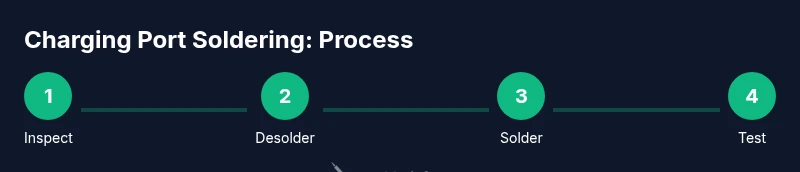
- 1
Inspect target area and plan the port replacement
Carefully inspect the charging port area and the surrounding traces. Note which pads are intact and whether any copper is lifted. Plan your replacement port alignment before touching the first joint, so you minimize risk of misalignment.
Tip: Take high-magnification photos to guide reassembly and verify pinout against the board schematic. - 2
Power down and disconnect all power sources
Power down the device completely, unplug any power adapters, and remove the battery if possible. This prevents accidental shorting and protects you from electrical shock while soldering.
Tip: Never work on live circuits; double-check that the power is fully disconnected before starting. - 3
Ground yourself and prepare the workspace
Set up an anti-static workstation with an ESD mat and wrist strap. Keep the area clean, well-lit, and free of metal jewelry that could bridge connections. Organize tools within easy reach and verify your replacement port is on hand.
Tip: Use a magnetized tray for tiny components to avoid losing pins. - 4
Identify the correct replacement port
Confirm the port type (USB-C, micro-USB, or other) and ensure the footprint and pinout match the device. If the footprint differs, you may need to adapt or rework the footprint area to fit the new port.
Tip: Refer to the device’s service manual or online schematics when possible. - 5
Desolder the old port
Apply flux to the joints, heat each pad with the soldering iron, and wick away the solder with desoldering braid. Work slowly to prevent pad lift and avoid overheating adjacent traces.
Tip: If a pad refuses to lift, apply a touch of hot air carefully to free it without damaging the board. - 6
Prepare pads and clean the footprint
Clean any residual solder and flux, inspect pad integrity, and ensure the footprint is flat and aligned with the new port. Any lifted pads might require repair before continuing.
Tip: Lightly abrade oxidized pad surfaces with a clean tip to improve current exchange. - 7
Position and solder the new port
Place the new port on the footprint, secure alignment with a small amount of flux, and tack corners of the port first. Then solder all pins with light, quick touches to avoid heat damage.
Tip: Solder the edge pins first to lock the port in place before finishing the center pins. - 8
Inspect joints and reflow if needed
Examine each joint for proper wetting and uniform fillets. Reflow any suspect joints with a brief touch of heat and flux if needed to fix any cold joints or bridges.
Tip: Use a magnifier to spot tiny bridging or dull joints that indicate poor wetting. - 9
Test the repaired port and diagnose power delivery
Use the multimeter to verify continuity from the port pads to the board traces. Test with a known-good charger and observe voltage delivery. If charging fails, recheck cable, battery health, and charging controller circuitry.
Tip: Perform a cautious power-on test with a current-limited supply to avoid damaging the device.
Quick Answers
What tools are essential for soldering a charging port?
Key tools include a fine-tipped soldering iron, lead-free solder, flux, desoldering braid, a multimeter, an anti-static setup, and a replacement port. An optional hot air station can help with stubborn joints.
You’ll need a fine-tipped iron, flux, solder, braid, a multimeter, anti-static gear, and a replacement port. A hot air station is optional for tough joints.
Can I solder a charging port without removing the motherboard?
In some devices you can access the port via flexible cables, but in most cases it's safer to detach the board to access pads without risking shorts or damage to nearby components.
Sometimes you can work through nearby cables, but often you should remove the board to access the pads safely.
What temperature should I use for soldering with lead-free solder?
Use a temperature appropriate for lead-free solder, typically in the 320–350°C range, and avoid prolonged heating to prevent pad damage.
Aim for around 320 to 350 degrees Celsius and keep heat sessions brief to avoid damaging the pads.
How do I test the port after rework?
Check continuity from port pins to board traces with a multimeter, then test charging with a known-good cable. Look for power delivery and absence of shorts.
First check continuity, then test with a good cable to confirm power delivery and no shorts.
What are common mistakes to avoid?
Avoid overheating pads, bridges between joints, and leaving flux residues. Misalignment can cause poor contact or damage to the traces.
Be careful not to overheat pads, bridge joints, or leave flux behind.
How long does this repair typically take?
Plan for about 60–120 minutes depending on access and device complexity. Practice and careful technique reduce time with experience.
Usually about an hour or two, depending on the device and how accessible the port is.
Watch Video
Top Takeaways
- Plan before you solder and verify port alignment
- Use flux to ensure clean, reliable joints
- Check for shorts and pad integrity after desoldering
- Test thoroughly with a known-good charger before final reassembly
- If pads lift, consider repair or board-level replacement