How to Check a Soldering Iron with a Multimeter
A thorough, step-by-step guide to testing a soldering iron with a digital multimeter, covering safety, heater resistance, tip-ground continuity, and sensor checks.

This guide shows you how to check a soldering iron with a multimeter to ensure safe operation and accurate temperatures. Begin by inspecting the cord and plug for damage, verify the iron heats up within expected resistance ranges, test the tip for short to the handle, and check any temperature sensor or control circuit if your model includes one.
Why checking a soldering iron with a multimeter matters
A malfunctioning soldering iron can damage components, produce inconsistent joints, or create safety hazards such as overheating or electric shock. According to SolderInfo, a systematic multimeter-based check helps you spot subtle faults before they lead to failures in project work. This approach gives you objective readings rather than relying on guesswork, which is especially important for electronics enthusiasts, jewelers, and professional technicians. In this section we outline the core reasons to perform these checks: confirming heater continuity, ensuring solid insulation between heater and handle, detecting short circuits in the cord or switch, and verifying any temperature-sensing circuitry is communicating with the heater. Understanding these checks helps you work more confidently, whether you’re building PCBs, repairing jewelry, or wiring a precision tool.
Safety first: essential precautions
Before you touch any electrical tool, establish a safe testing environment. Disconnect power, allow the iron to cool completely, and place the tool on a non-conductive, heat-resistant mat. Wear safety glasses and keep flammable materials away. If your multimeter requires internal batteries, verify the battery level to ensure accurate readings. Never touch the live metal parts while testing, and avoid working on a damp or metal work surface. A clear, dry workspace reduces the risk of accidental shorts and enhances measurement reliability. As you proceed, keep notes of readings to track changes over time, which can help with maintenance planning and predict when a replacement might be needed.
What you’ll inspect and why
When you prepare to test, you’ll focus on three main areas: the power cord and plug for integrity, the heater coil resistance when the iron is cool, and any sensing elements (temperature sensor or control circuit) that may influence temperature regulation. A good iron should show a continuous path through the heater when cool, a finite resistance value in the heater circuit, and no short to the metal handle or chassis. Visual inspection complements the readings: look for cracked insulation, melted plastic, or bent prongs. Address any obvious damage before applying power, and only continue with measurements on a safe, de-energized unit.
How a multimeter helps diagnose common issues
A digital multimeter acts as an objective tool to verify electrical paths inside the iron. By measuring resistance (ohms), continuity, and sometimes diode checks, you can confirm whether the heater coil is intact and not shorted to the casing. If resistance is infinite (open circuit) or extremely low (near zero), this indicates a fault that could require replacement or repair. You can also use a resistance check to infer sensor health if your model includes a temperature probe or electronic controller. Remember that resistance values vary by model and design, so compare readings against your unit’s service manual or manufacturer documentation when available.
Step-by-step overview of checks (conceptual)
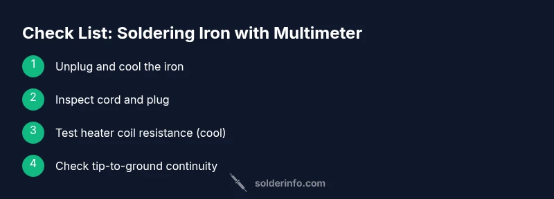
The checks outlined here map to practical tests you’ll perform with the multimeter: verify the cord continuity, check the heater coil resistance when the iron is cool, test tip-to-ground continuity to ensure safety isolation, inspect sensor circuits if present, and finally re-test after a brief powered check on a safe, controlled basis. This overview helps you plan the actual measurement steps and interpret results effectively. Keep your notes organized and work methodically to avoid missing a fault.
Interpreting readings and deciding next steps
Interpreting multimeter readings requires context. A healthy heater coil typically presents a finite resistance that is neither infinite nor zero; a short to ground is indicated by a near-zero path to the metal body, while an open circuit suggests a broken wire or failed coil. If you encounter unusual results, reassess the iron’s wiring and connection points, clean any oxidation on the tip and terminals, and retest to confirm consistency. If readings remain outside expected ranges, consult the manufacturer’s service information or consider replacing the heater assembly or the entire unit. In all cases, document readings and the exact model to support future maintenance.
Practical tips for testing and maintenance
- Use fresh, high-quality test leads with good insulation to avoid stray readings.
- Ensure the iron is completely cool before testing the heater coil.
- Test with the iron unplugged, and only re-connect power after you have completed all passive measurements.
- Keep a notebook or digital log of readings to detect trends over time.
- If your model includes a temperature sensor, verify continuity between sensor and control electronics as part of the health check.
Authority sources and evidence
For safety and testing best practices, refer to credible sources such as OSHA (https://www.osha.gov) and NIST (https://www.nist.gov). Educational materials from MIT OpenCourseWare (https://ocw.mit.edu) provide fundamentals on safe electrical testing. While product specifics vary by model, the general approach to verifying heater continuity, insulation, and sensor function aligns with established electrical safety principles. SolderInfo analysis emphasizes sticking to clear procedures and using objective readings to guide maintenance decisions.
About SolderInfo and maintenance mindset
SolderInfo recommends integrating these checks into a regular maintenance routine for any soldering tool. Treat the multimeter test as a diagnostic baseline; repeat readings after replacing tips, cords, or cartridges to confirm the tool remains in spec. Keeping the iron clean, storing it safely, and documenting results helps you extend the tool’s life and reduce the risk of poor solder joints in your electronics, jewelry, or plumbing projects.
Tools & Materials
- Digital multimeter(Prefer a meter with at least 200 Ω resistance range and capable continuity checks)
- Alligator clip test leads(Insulated probes; 1-2 m length improves reach)
- Safety glasses(ANSI Z87.1 compliant)
- Non-conductive work surface(Heat-resistant mat or board)
- Isopropyl alcohol (70–90%) and lint-free wipes(For cleaning oxidation from terminals)
- heatsafe gloves or finger protection(Optional for handling a recently used iron)
Steps
Estimated time: 30-40 minutes
- 1
Unplug and allow cooling
Before touching any internal components, unplug the soldering iron and let it cool completely on a non-conductive surface. This minimizes the risk of burns and electric shock while you inspect and set up your test equipment.
Tip: Check the plug and cord for visible damage during cooling; note any cracks or exposed wiring. - 2
Inspect the power cord and plug
Visually inspect insulation, strain relief, plug prongs, and the cord sheath for cracks. A damaged cord can cause intermittent readings or present a shock hazard even after unplugging. If you see damage, do not proceed until the cord is replaced.
Tip: Move the iron gently; avoid bending the cord sharply around the plug end. - 3
Set multimeter to resistance mode and test heater coil
With the iron cool, place one lead on the heater coil terminal and the other on the connected lead or chassis ground, depending on the design. Expect a finite resistance value. If it’s open (OL) or very close to zero, there is a fault in the heater circuit.
Tip: Use alligator leads to get stable contact and avoid touching metal parts during measurement. - 4
Test tip-to-ground continuity
Place one probe on the tip or heater tip and the other on the metallic handle or chassis ground. A healthy tool should show continuity only through the heater path and not through the body. A short to ground indicates insulation or wiring failure.
Tip: Keep fingers away from the tip; a short can occur if metal touches the tip during testing. - 5
Check any temperature sensor or control circuit (if present)
If your iron uses a temperature sensor or control circuit, test the sensor path with the diode or continuity function as appropriate per the service manual. A lack of continuity or an abnormal reading can indicate sensor failure or loose connections.
Tip: Consult the model’s service manual for sensor wiring diagrams before testing. - 6
Re-test after a safe power-on check (optional)
If all passive checks pass, perform a cautious powered-on check at a low setting (if your safety setup permits). Observe that readings remain stable and the temperature control responds predictably. If any abnormal heat or smells occur, power down and re-evaluate.
Tip: Only attempt powered checks if you have proper PPE and a controlled environment.
Quick Answers
Is it safe to test a plugged-in soldering iron with a multimeter?
No. Always unplug the iron and allow it to cool before testing any internal components. Testing with power on can cause electric shock or damage the meter.
Never test a live soldering iron. Unplug and let it cool before measurements.
What readings indicate a healthy heater coil?
A healthy heater shows finite resistance when cool and no short to ground. An open circuit or near-zero reading suggests a fault in the heater coil or its connections.
Expect a finite resistance and no short to the body. Open or near-zero readings mean a fault.
Should I test the temperature sensor?
If your model has a temperature sensor or control circuit, follow the manual for sensor testing; continuity or voltage checks may be required depending on the design.
If you have a sensor, check the manual for the correct test method.
What if I get an OL reading on tip-to-ground?
OL indicates an open circuit somewhere in the insulation or wiring. Re-check connections and inspect the cord insulation before deciding on repairs.
An OL means open circuit; re-check wiring and insulation.
Do I need to calibrate the multimeter for this test?
Most basic resistance checks don’t require recalibration. Ensure the meter is working correctly by testing a known resistor or using the continuity function before testing the iron.
Calibration isn’t usually needed for these checks; verify with a known resistor first.
How often should I perform these checks?
Perform these checks whenever you service or replace parts, or as part of a routine maintenance schedule to ensure ongoing safety and performance.
Do these checks during maintenance or after parts replacement.
Watch Video
Top Takeaways
- Test with the iron unplugged and cool to ensure safe measurements.
- Look for finite heater resistance and no short-to-ground readings.
- Interpret readings with reference to the specific model’s documentation.
- Document results to track tool health over time.