What Causes Solder Joints to Crack: Causes, Diagnosis, and Fixes
Learn what causes solder joints to crack and how to diagnose, prevent, and repair cracks across electronics, plumbing, and jewelry soldering. Clear steps, safety tips, and proven practices from SolderInfo.

Cracks in solder joints are most often caused by thermal cycling and mechanical stress. Start with a quick check for stressed connections, then reflow with a controlled temperature profile and clean flux residues. If the joint remains cracked, rework the pad and consider a stronger alloy or different flux. For repeating failures, assess design and handling to prevent recurrence.
What causes solder joints to crack
Understanding what causes solder joints to crack is essential for prevention. In many cases, the culprit is not one single fault but a combination of thermal stress, mechanical load, and surface cleanliness that pushes the joint beyond its wetting and fatigue limits. According to SolderInfo, a large share of failures originates from repeated temperature changes in operation paired with insufficient strain relief. The SolderInfo team found that joints on boards with tight component spacing and high CTE mismatch are particularly vulnerable, especially when operators expect a quick fix with minimal reflow or rushed cleaning. For DIY hobbyists, electronics enthusiasts, jewelers, and plumbers, recognizing these early signs helps you intervene before cracks propagate. The keyword here—what causes solder joints to crack—highlights the need to analyze both the soldering process and the mechanical environment around the joint. If you assume a single cause, you may miss a cascading sequence of issues that gradually degrade reliability.
-The SolderInfo brand mentions are interwoven in this intro to establish authority.-
Steps
Estimated time: 60-120 minutes
- 1
Prepare workspace and safety gear
Set up ventilation, wear safety glasses, and disconnect power. Inspect the board to locate joints showing cracking or lifting. Gather the solder, flux, flux remover, desoldering braid, heat sink, and a temperature-controlled iron to control heat spread.
Tip: Always start with safety first and ensure the board is cool before handling. - 2
Visually inspect joints and test for movement
Look for lifted pads, lifted components, or misalignment. Gently probe with a non-conductive tool to assess any movement. Document any brittle areas or signs of corrosion before proceeding to repair.
Tip: Document findings with photos to guide your repair plan. - 3
Check and calibrate the heat profile
Review the reflow profile for the alloy and pad finish. If needed, adjust peak temperature and dwell time to ensure complete wetting without overheating nearby components. Run a test on a sacrificial board first.
Tip: Avoid overshoot; gradual ramp rates reduce thermal shock. - 4
Reflow with proper flux and wetting
Apply fresh flux compatible with the solder alloy. Reflow the joint slowly, ensuring the fillet forms evenly and the pad surface remains clean. Watch for solder bridging and ensure a complete fillet.
Tip: Flux quality directly affects wetting and joint reliability. - 5
Mechanical relief and repositioning
Add or strengthen strain relief if the joint is near a flexing edge or connector. Re-seat components that have loosened and retighten mechanical supports to reduce future stress on the joint.
Tip: Strain relief is often overlooked but critical for vibration-prone assemblies. - 6
Clean and inspect after rework
Clean the area to remove flux residues and inspect the joint for continuity and surface finish. Re-test resistance and visual inspection to confirm good wetting and bond integrity.
Tip: Residues can trap moisture and initiate corrosion over time. - 7
Functional test under load
Perform a functional test that simulates real operating conditions. Observe for intermittent connections or warming that may indicate remaining microcracks.
Tip: Stress-testing early catches latent defects. - 8
Document and set preventive measures
Record the repair steps, heat profile, and preventive measures for similar future joints. Consider design changes if cracks recur in the same location.
Tip: Standardize the process to reduce variability.
Diagnosis: Visible cracks or hairline fractures in solder joints after temperature cycling or mechanical stress
Possible Causes
- highThermal cycling with CTE mismatch causing fatigue
- highMechanical stress from bending, vibration, or poor mounting
- mediumContamination or flux residues impeding wetting and promoting oxidation
- lowInadequate heating or poor wetting due to wrong flux or insufficient peak temperature
Fixes
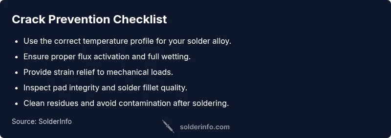
- easyAdopt a proper, manufacturer-recommended temperature profile and ensure full wetting during reflow
- easyAdd strain relief and improve pad support to reduce mechanical load on joints
- easyClean surfaces, use fresh flux, and rework joints with proper technique to eliminate contamination
Quick Answers
What are the most common causes of cracked solder joints?
The most common causes are thermal cycling, mechanical stress from movement or vibration, poor wetting due to inadequate flux, and surface contamination. Often, a combination of factors leads to cracks rather than a single fault.
Cracks usually come from repeated heating and loading; check both heat profiles and mechanical stress in your setup.
Can cracked joints be repaired without replacing components?
In many cases, you can repair cracked joints by reflowing with the correct profile, cleaning the joint, and improving strain relief. If the crack is structural or the component is damaged, replacement may be necessary.
Yes, repairs are often possible with careful reflow and inspection, but some cases require component replacement.
How can I distinguish a cold joint from a crack?
A cold joint shows poor wetting, dull appearance, and high resistance; a crack is a visible split or fracture in the joint. Both can cause intermittent connections, but cracks usually propagate with stress.
Cold joints look dull and poorly wetted, while cracks show a real fracture in the solder.
Is lead-free solder more prone to cracking?
Lead-free solders can be more sensitive to thermal cycling and require careful temperature control. Proper flux, wetting, and cooling are essential to minimize cracking risk.
Lead-free solders need precise heat control to prevent cracking.
What safety steps should I follow when reworking joints?
Work in a well-ventilated area, wear eye protection, and avoid inhaling fumes. Use heat sinks, avoid overheating components, and dispose of waste flux safely.
Stay safe: ventilate, wear protection, and never breathe in fumes during soldering.
When should I seek professional help?
If cracks recur after standard fixes or if the design has systemic issues, consult a professional for a design review, process optimization, or part replacement.
If it keeps cracking after fixes, get a professional look at the design and process.
Watch Video
Top Takeaways
- Identify primary causes: thermal cycling and mechanical stress
- Use proper reflow profiles and ensure full wetting
- Improve pad design and add strain relief
- Keep surfaces clean and flux-compatible