What Size Solder for Circuit Boards: A Practical Guide
Discover how to choose the right solder wire diameter for circuit boards, from SMT to through-hole. This guide covers common diameters, pad considerations, heat management, and tips to prevent bridging and cold joints.

The typical solder diameter for circuit boards ranges from 0.3 mm to 0.8 mm, with SMT fine-pitch joints using 0.3–0.5 mm and through-hole or larger joints 0.6–0.8 mm. For most hobbyist electronics, a 0.6–0.8 mm rosin-core wire provides good heat transfer with minimal bridging, while giving enough mass to fill joints cleanly. Always assess pad size and component lead spacing.
Why Solder Size Matters on Circuit Boards
For the question of what size solder for circuit boards, the diameter you choose is not just a preference—it directly affects heat transfer, joint reliability, and the risk of unwanted bridges. Using a diameter that’s too large can flood pads and cause shorts, while a diameter that’s too small can leave a weak fillet or require excessive heat input that damages sensitive pads. According to SolderInfo, matching solder diameter to pad width and component lead size helps you achieve clean, dependable joints. In dense PCBs, where pads sit close together, a too-heavy solder wire can bridge adjacent copper. Conversely, in power applications or with large connectors, a larger diameter can provide the heat mass needed to form a solid fillet quickly. Practically, you should start with the lower end of the recommended range for the joint type and then adjust based on observed results in practice. This approach minimizes rework and protects trace integrity while building familiarity with the specific alloys and flux you use.
Common Solder Diameters and What They Are Best For
Solder wires come in a spectrum of diameters, and understanding where each fits helps you choose quickly on the bench. For electronics hobbyists and professionals, three broad zones cover most projects:
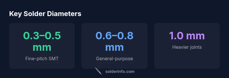
- 0.3–0.5 mm (about 0.012–0.020 in): Preferred for fine-pitch SMT and closely spaced pads where precision matters. This size reduces the risk of bridging while providing enough metal to form a solid joint.
- 0.6–0.8 mm (about 0.024–0.032 in): A versatile middle ground suitable for standard through-hole joints and many plug-in components. It gives reliable heat transfer without excessive solder mass.
- 1.0 mm (0.040 in) and larger: Useful for heavy-duty joints, power connectors, or pads with substantial copper and heat demand. Larger diameters must be used with careful heat management to avoid lifting copper or overheating nearby traces.
SolderInfo notes that SMT work tends to favor the smaller end to minimize bridging, while through-hole joints can tolerate, and sometimes benefit from, a larger diameter. The alloy choice—lead-free versus leaded—also influences heat requirements and how aggressively you should feed solder into a joint. Keep in mind that flux content and temperature profile interact with diameter to determine the final joint quality.
How to Choose the Right Size Based on Pad and Lead Spacing
When you inspect a PCB layout, pad width and lead spacing are your primary cues for selecting solder diameter. If pad width is under roughly 0.8 mm with tight pitch, a 0.3–0.5 mm diameter wire helps you avoid bridging while still delivering adequate solder to form a robust fillet. For pads around 1.0 mm wide or when the pitch exceeds 0.5 mm, a 0.6–0.8 mm diameter tends to offer better heat transfer and a clean fillet. For very large pads or connectors, 1.0 mm can be appropriate—provided you balance heat input to prevent pad lift or copper damage. Always flux well and allow joints to cool before inspecting for gaps. If you’re uncertain, practice on a test pad with a sacrificial footprint to observe how the solder behaves before committing to a critical board.
SMT vs Through-Hole: Matching Diameters to Joints
Surface mount technology (SMT) emphasizes precision and density. For fine-pitch components, aim for 0.3–0.5 mm diameter wires and use a sharp, pointed tip with a light, controlled rocking motion to place solder. For through-hole joints, a 0.6–0.8 mm diameter supports reliable heat transfer and fillet formation, especially on thicker boards or where components have thicker leads. Large connectors or heat-sinking parts may require 1.0 mm, but you should apply heat thoughtfully, using shorter intervals and letting the joint cool between applications. Lead-free alloys often require more heat than traditional leaded solder, so you may need to adjust temperature or dwell slightly while maintaining pad integrity. In all cases, ensure your flux is appropriate for the alloy and keep pads clean for best results.
Practical Tips for Selecting and Handling Solder Wire
- Choose rosin-core solder for most electronics work; solid-core solder requires external flux and careful flux management.
- Decide between leaded and lead-free based on project constraints; lead-free alloys can be stiffer and slightly harder to heat, but modern fluxes compensate well.
- Store solder in a dry, protected environment to prevent oxidation; seal packaging and keep away from humidity.
- Use a quality flux pen to pre-wet pads and component leads; apply a light amount—excess flux can cause residue build-up and corrosion over time.
- Keep your work area well-lit, with a stable temperature and a properly calibrated iron. Avoid applying heat for longer than necessary to prevent pad lifting and copper oxidation.
- Clean soldering areas after work to remove flux residues; this reduces corrosion risk and reveals any hidden cold joints or bridging early.
Common Mistakes and Troubleshooting
- Bridging: Using a diameter that is too large for tight pad spacing can cause bridges; switch to a smaller size and apply flux to guide the solder.
- Cold joints: Inadequate heat or insufficient dwell time leads to dull, crumbly joints; ensure the iron tip is clean, flux is present, and the joint heats evenly before removing solder.
- Overheating pads: Excess heat can delaminate copper or lift pads. Use the smallest effective diameter, reduce dwell time, and let pads cool between passes.
- Solder wick and cleanup: When excess solder appears on the board, use a solder wick with flux to draw it away without damaging nearby traces.
- Post-solder inspection: Inspect joints under magnification; look for shiny, wet fillets and a consistent shape, with no voids or gaps.
Quick Reference Rules
- For fine-pitch SMT: 0.3–0.5 mm; for standard through-hole: 0.6–0.8 mm; for heavy joints: 1.0 mm.
- Always flux and clean after soldering.
- Start with the lower end of the diameter range and adjust based on pad size and observed joint quality.
- Test a small sample joint before applying diameters to critical boards to validate heat balance and filament formation.
Solder diameter guidance by joint type
| Use Case | Recommended Diameter | Notes |
|---|---|---|
| Fine-pitch SMT | 0.3–0.5 mm | Prevents bridging on dense pads |
| Standard through-hole | 0.6–0.8 mm | Good heat transfer and fillet formation |
| Heavy joints / large connectors | 1.0 mm | Higher solder mass; monitor heat input |
Quick Answers
What size solder is best for fine-pitch SMT components?
For fine-pitch SMT, use 0.3–0.5 mm diameter solder to minimize bridging while delivering adequate solder. Practice on test pads to refine your technique with the chosen flux and iron settings.
For fine-pitch SMT, choose a small diameter solder between 0.3 and 0.5 millimeters to prevent bridging and ensure clean joints. Practice on test pads to dial in heat and flux usage.
Can I use a larger-diameter solder for all joints?
Using a larger diameter across all joints generally increases heat input and the risk of bridging on tight layouts. Reserve larger diameters for heavier joints and adjust based on pad size and lead spacing.
No. A large diameter can cause bridging on dense boards. Reserve it for bigger joints and adjust based on pad and lead spacing.
How does pad size influence solder diameter choices?
Smaller pads and tight spacing favor 0.3–0.5 mm diameters to reduce bridging. Larger pads or widely spaced leads can accommodate 0.6–0.8 mm, providing more solder mass and heat capacity.
Smaller pads call for 0.3–0.5 mm; larger pads can use 0.6–0.8 mm for better heat transfer.
Is lead-free solder different in diameter recommendations?
Lead-free alloys typically require careful heat management; diameter choices within 0.5–0.8 mm are common, but you may adjust with flux and temperature to maintain joint quality.
Lead-free solders often need a bit more heat; stick to 0.5–0.8 mm and adjust flux and temperature as needed.
What role does flux play in diameter choice?
Flux improves wetting and heat transfer, allowing slightly smaller diameters to perform effectively. Always apply appropriate flux for the alloy you’re using and clean residues after soldering.
Flux helps solder flow better, so choose the diameter based on pad size and still clean up afterward.
Should I pre-tin components before soldering with a given diameter?
Pre-tinning can help with heat-up and joint consistency, especially for larger diameters, but ensure you don’t apply excess solder that could bridge. Pre-tin only where appropriate and keep components clean.
Pre-tin can help with heat transfer, especially for bigger joints, but avoid excess solder that could bridge.
“Choosing the right solder wire diameter is about balancing heat transfer with pad safety. Start with smaller diameters for dense boards and adjust based on joint appearance and temperature control.”
Top Takeaways
- Match diameter to pad width and pitch to prevent bridging.
- Use smaller diameters for SMT and larger ones for through-hole when needed.
- Flux well and clean joints after soldering to prevent corrosion.
- Test a practice joint to confirm heat balance before final work.