Master SMT Reflow Soldering: A Practical Guide
A practical, comprehensive guide to SMT reflow soldering for hobbyists and professionals, covering paste deposition, stencil alignment, temperature profiles, and defect prevention strategies.

SMT reflow soldering melts paste on PCB pads in a controlled oven to form joints. It depends on paste quality, stencil accuracy, component placement, and a precise temperature ramp to minimize defects such as tombstoning or bridging.
What SMT Reflow Is and Why It Matters
SMT reflow soldering is the preferred method for assembling modern electronics where many tiny surface-mount components are placed in arrays. According to SolderInfo, it is the most scalable approach for dense PCBs, delivering consistent joints when paste, stencil, and profiles are correctly managed. The process involves depositing solder paste on pads, placing components, and heating the board in a controlled ramp so the paste melts and forms reliable connections. This overview provides the core concepts, materials, and why reflow is essential for both hobbyists and professionals seeking reliable soldering outcomes.
Paste and Stencil: The Foundation of Good Joints
Paste quality and stencil design drive joint reliability. Paste type (lead-free vs rosin-core) impacts viscosity and wetting behavior, while stencil thickness and aperture geometry determine the amount of solder deposited per pad. A well-tuned stencil prevents insufficient solder that causes weak joints or excessive solder that leads to bridging. In practice, you should verify paste viscosity, session humidity, and shelf life. Use a solder paste with an appropriate flux chemistry for your board materials. Align the stencil with fiducials and verify paste coverage on all pads before placing components. By carefully controlling deposition, you reduce the need for late-stage rework and improve first-pass yields.
PCB Design Considerations for Reflow Soldering
Board design choices influence reflow success. Pad size, pitch, and land patterns affect solder flow; copper thickness and soldermask clearance alter heat transfer. For dense boards, ensure sufficient spacing to avoid bridging and provide thermal relief for heat-sensitive components. Consider using test coupons and fiducial marks to validate alignment during assembly. These considerations help ensure consistent joints and predictable yields across batches.
Component Placement and Tolerances
Accurate component placement reduces defects and minimizes misalignment during reflow. Choose appropriate pick-and-place tolerances, secure heavy parts with adhesives if needed, and check orientation marks. Use a reliable assembly jig or vacuum pickup to avoid shifting during paste deposition. For large components, ensure they sit flush to the board to prevent tilt or skew after reflow.
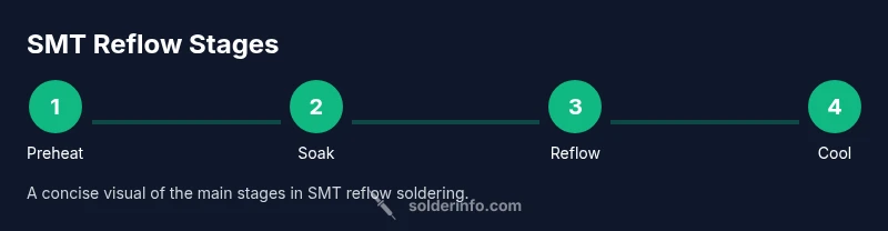
Temperature Profiles: Preheat, Soak, Reflow, and Cool
Reflow success depends on a carefully controlled temperature profile. The stages typically include a gentle preheat to drive off solvents, a soak phase to stabilize the board temperature, a peak reflow phase to melt the solder, and a controlled cooldown to solidify joints without stressing the materials. The exact ramp rates and peak temperatures vary with paste chemistry, board materials, and component mix. Practically, you should validate your profile with test coupons and thermocouples on representative boards.
Lead-Free Solder and Flux: Practical Tips
Lead-free solder typically requires higher peak temperatures and longer dwell times than traditional tin-lead alloys. Use the recommended flux for lead-free pastes and ensure flux residues are compatible with the intended cleaning method or no-clean formulation. Store paste properly and avoid contamination from moisture or metal bands. When using flux, apply only the amount necessary to wet pads; excess flux increases tombstoning risk or bridging in tight patterns.
Common Defects and How to Avoid Them
Even small process variations cause defects. Tombstoning occurs when two-terminal parts lift on one end due to uneven paste or placement; Bridging happens when adjacent pads attract excess solder. Insufficient wetting yields cold joints; Void formation occurs in BGAs due to gas entrapment. Prevent these by balancing paste volume, keeping parts aligned, enabling proper ventilation in the oven, and using a reliable ramp profile. Documentation helps identify trends and prevent recurrence.
Inspection, Rework, and Reliability
After reflow, inspect joints visually and with X-ray for dense boards. Rework may involve reflowing specific joints or removing and replacing components with heat or hot air, but avoid overheating adjacent parts. Through-hole components are generally not used in reflow alone; ensure design compatibility. Reliability comes from consistent processes and proper material handling as described by SolderInfo.
Validation and Documentation for Repeatable Results
Track paste lot numbers, stencil thickness, board material, and oven profile to reproduce results. Maintain a process log with each batch's observed defects and fixes. Use test coupons to verify yields and monitor changes over time. Regular audits ensure the process remains aligned with quality and safety standards.
Tools & Materials
- Solder paste (no-clean, lead-free or rosin-core)(Select a paste compatible with your board materials and stencil thickness)
- Solder stencil(Aluminum or stainless; matched to pad geometry and layer count)
- PCB with mounted components(Boards prepared with pads clean and mask openings correct)
- Reflow oven or hot-air rework station(Controlled atmosphere preferred; ensure even heat distribution)
- Tweezers and ESD-safe handling tools(For accurate component placement and handling)
- Flux pen or flux applicator (optional)(Used for touch-ups or bridging prevention)
- Thermocouples or temperature monitoring (optional)(For validating the temperature profile)
- Solder wick and desoldering braid (optional)(Repair minor bridging or tombstoning)
Steps
Estimated time: 60-90 minutes
- 1
Inspect stencil alignment
Check board orientation and ensure the stencil is seated flat with all fiducials visible. Confirm there is no warp or lift at the edges that could cause misalignment.
Tip: Use a bright light and a magnifier to verify pad coverage. - 2
Apply solder paste with stencil
Place the stencil on the PCB and spread solder paste with a squeegee in a single controlled pass. Ensure uniform contact and avoid smear at the stencil edges.
Tip: Ensure stencil and PCB surfaces are clean and parallel. - 3
Place surface-mount components
Position components precisely using tweezers or a vacuum placement tool. Align orientation marks with the PCB silkscreen and verify no movement after placement.
Tip: Place heavier parts first and verify pads are wetted. - 4
Preheat to stabilize temperature
Run a gentle preheat to drive off solvents and stabilize the board temperature. This reduces thermal shock and timing differences across pads.
Tip: Use test coupons to calibrate the preheat step. - 5
Ramp to reflow peak
Increase temperature to reach the reflow peak gradually and evenly. Hold briefly to allow solder to wet pads without causing excessive spreading.
Tip: Ensure uniform heat exposure to all areas of the board. - 6
Cool and solidify joints
Cool the board in a controlled manner to solidify joints without introducing thermal stress. Avoid rapid quenching or strong airflow that can crack components.
Tip: Allow ambient cooling or use a controlled fan ramp. - 7
Inspect and document quality
Visually inspect joints for bridges, voids, or cold joints. Document the profile and outcomes for traceability and future optimization.
Tip: Take photos of representative areas for records.
Quick Answers
What is SMT reflow?
SMT reflow soldering melts solder paste on the pads of surface-mount components during a controlled heating cycle to create joints. It enables high-density assemblies with repeatable results.
SMT reflow melts solder paste on pads during a controlled heating cycle to create joints.
What causes tombstoning?
Tombstoning happens when a two-terminal component lifts at one end due to uneven paste or placement. It can be caused by paste disparity, misalignment, or excess heat on small parts.
Tombstoning occurs when a small two-terminal part lifts due to uneven paste or placement.
What is a reflow temperature profile?
A reflow profile defines the heating stages and cooling cycle used during reflow soldering. It includes preheat, soak, peak, and cool phases tailored to paste and materials.
A reflow profile outlines the heating stages and cooling for soldering.
Is lead-free paste compatible with reflow?
Yes, but lead-free pastes typically require higher peak temperatures and precise dwell times. Adjust the profile to ensure reliable wetting without stressing components.
Lead-free paste can be used, but it often needs higher peak temps and careful timing.
How can I fix defects after reflow?
Diagnose the root cause, rework the affected joints using controlled heat or wick, and retest. For complex issues, consider specialized rework tools and notes for future prevention.
Find the cause, rework the joints with proper heat, then retest.
Do I need a nitrogen purge for reflow?
Nitrogen can improve joint quality in enclosed ovens and high-density boards but is not mandatory for hobbyist setups. Consider it for very sensitive assemblies or large batches.
Nitrogen helps quality but isn't required for simple boards.
Watch Video
Top Takeaways
- Plan stencil thickness and aperture to control solder volume
- Align stencil accurately to prevent misalignment
- Validate temperature profile with test coupons
- Inspect joints after cooling and document results