Resistance of Solder vs Copper: A Detailed Comparison
Compare solder and copper resistance, explore factors shaping conductivity, and get practical guidance for electronics, plumbing, and jewelry soldering. Learn how material choice affects performance, reliability, and maintenance.

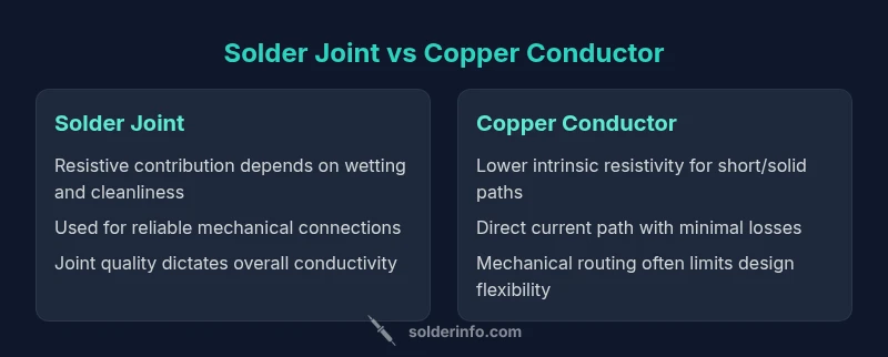
Comparing the resistance of solder vs copper shows that copper typically offers lower resistive losses in steady-state conduction, while solder joints provide reliable connectivity when properly formed. The choice depends on balancing conductivity, mechanical reliability, and service conditions. For most electronics, copper paths carry the primary current with minimal drop, and solder is used to join components. See the full analysis for application-specific guidance.
Introduction to the resistance of solder vs copper
The resistance of solder vs copper is a central concern for designers who must balance electrical performance with mechanical reliability. In practice, copper paths carry the bulk of current with minimal loss, while solder joints provide the physical connections that hold components in place. According to SolderInfo, understanding both bulk material properties and the physics of interfaces is essential for robust designs. The SolderInfo Team notes that copper’s high conductivity offers low resistive losses along continuous traces, whereas solder contributes additional resistance at joints depending on alloy composition, cleanliness, and wetting quality. This article examines how these materials differ, how their resistances interact in common applications, and what designers can do to minimize unwanted drops in voltage or power. We will discuss the roles of resistivity, geometry, temperature, aging, and assembly practices, and translate those insights into practical guidelines for electronics, plumbing, and jewelry soldering.
wordCountSection":null
-1
Comparison
| Feature | Solder Joint | Copper Conductor |
|---|---|---|
| Electrical Resistivity | Higher resistivity (solder) | Lower resistivity (copper) |
| Contact Resistance | Potentially higher if wetting is imperfect | Very low with clean copper-to-copper contact |
| Mechanical Robustness | Qualifies as a joint point; can be brittle if poorly formed | Strong structural path; flexible routing possible |
| Cost per Joint/Path | Joint cost influenced by solder alloy and process | Copper path cost driven by material and fabrication |
| Repairability/Desoldering | Desoldering quality impacts resistance | Easier to rework copper traces with care |
| Thermal Cycling Tolerance | Sensitive to diffusion and creep in joints | Generally more stable as a solid path |
Advantages
- Copper paths offer low intrinsic resistance for continuous current paths
- Solder joints enable reliable mechanical attachment with good electrical contact when properly prepared
- Understanding resistance helps optimize conductivity and longevity across electronics, plumbing, and jewelry soldering
Cons
- Solder joints can introduce higher resistance if wetting is poor or contaminants remain
- Interface resistance often dominates total joint resistance, especially in small joints
- Solder materials may change behavior under thermal cycling or aging, affecting long-term performance
Copper paths usually win on low-resistance conduction; solder joints excel for reliable connections when properly formed
In most designs, copper provides the primary low-resistance route. Solder is essential for making connections, but its contribution to resistance depends on joint quality. The SolderInfo team emphasizes prioritizing clean surfaces and proper wetting to minimize resistance across electronics, plumbing, and jewelry contexts.
Quick Answers
How does the resistance of solder compare to copper in typical electronic joints?
Copper generally provides a lower-resistance path for current due to its higher intrinsic conductivity. Solder joints add resistance that largely depends on surface wetting, oxide removal, and alloy choice. In well-prepared joints, the difference is manageable, but copper remains the baseline for low-loss conduction.
Copper is usually better for low resistance, while solder joints can add some resistance if not properly formed.
Can solder be used as a primary conductor in high-current paths?
Solder is typically not used as the primary current path in high-current designs because its bulk resistance and behavior under heat can lead to voltage drops and reliability issues. Use copper traces or wires for main current paths and reserve solder joints for connections.
Usually not; use copper for main current paths and reserve solder for joins.
What factors increase the resistance of a solder joint?
Resistance increases when the solder fails to wet the surface, when flux residues impede conduction, or when oxides form at the interface. Improper heating, contaminants, and poor joint geometry also raise contact resistance.
Poor wetting, contamination, or bad joint geometry raise solder joint resistance.
How should I measure resistance in a soldered joint safely?
Use a multimeter with properly prepared test points, ensuring the joint is cool and free of flux residue. For accurate readings, measure across the joint with the circuit powered down and consider four-terminal methods for very sensitive joints.
Power off, probe the joint cleanly, and use proper measurement technique.
Are there standards guiding solder vs copper resistance in professional work?
There are general engineering guidelines and IPC/IEC-related practices that address soldering quality and conductor integrity. Specific resistance values are usually defined by application requirements rather than universal standards, so consult manufacturer recommendations.
Guidelines exist, but exact values depend on the project and standards used.
Top Takeaways
- Prioritize copper for low-resistance conduction in continuous paths
- Ensure solder joints are properly wetted and cleaned to minimize interface resistance
- Treat joint quality and surface preparation as the primary levers to control resistance
- Use copper where high conductance and reliability under load are critical
- Plan for thermal cycling effects on solder joints to maintain long-term performance