How to Solder a USB Connector: A Practical Guide
Learn how to solder a USB connector safely and reliably. This guide covers preparation, tool selection, step-by-step techniques, inspection, and testing for both PCB-mounted and cable-end USB connectors.

You will learn how to solder a USB connector to a PCB or cable end with a safe, reliable joint. This guide covers preparing the connector, selecting solder and flux, tinning wires, positioning the USB plug, and testing for continuity. Essential gear includes a fine-tip soldering iron, flux, solder, a multimeter, and a steady work surface.
Safety and Preparation
Before you begin soldering a USB connector, set up a clean, ESD-friendly workspace with good lighting and ventilation. Use a grounded mat or wrist strap to prevent static damage to sensitive components. Keep a dedicated, small-soldering iron stand and a fume extractor or fan nearby. According to SolderInfo, preparation is the foundation of reliable joints: clean surfaces, the right temperature, and a tidy work area reduce mistakes and improve heat transfer. As you plan, map out the connector orientation and identify which pins will be connected to power, ground, and data lines. This forethought minimizes wiring tangles and helps you avoid accidental shorts or bridge gaps when you apply solder.
While you prepare, ensure you have a comfortable stance and a steady hand. A poor posture or a busy bench invites tremor and misalignment. In 2026, best practices emphasize patience and deliberate movements over rushed soldering. Use magnification if you need to inspect tiny pads, and confirm your safety gear—goggles, gloves if handling sharp tools, and proper ventilation. The goal is to minimize heat exposure on plastic housings that can soften or deform under excessive heat, especially with USB-C connectors that have many pins and a dense footprint.
note2
Tools & Materials
- Soldering iron with a fine, conical tip(15-30 W for through-hole or fine-pine SMD work; temperature control preferred (350-370°C for lead-free solder; adjust for your alloy))
- Flux (rosin-core or no-clean flux)(Flux improves wetting and prevents oxidation. Apply a small amount to pads and wires.)
- Lead-free solder wire (0.5–0.8 mm)(SnAgCu (SAC) or SnCu; smaller diameter helps with precision on USB pads.)
- Flux brush or needle-application tool(For precise flux placement on pads and wire strands.)
- Solder wick/desolder braid(Use to remove excess solder or correct mistakes.)
- Magnifying loupe or microscope(Helpful for inspecting tiny USB pad joints.)
- Helping hands or PCB vise(Keeps the USB connector stable while you solder.)
- Multimeter or continuity tester(To verify continuity and detect shorts after soldering.)
- ESD protection (wrist strap, grounded mat)(Protect sensitive data/power lines from static discharge.)
Steps
Estimated time: 45-90 minutes
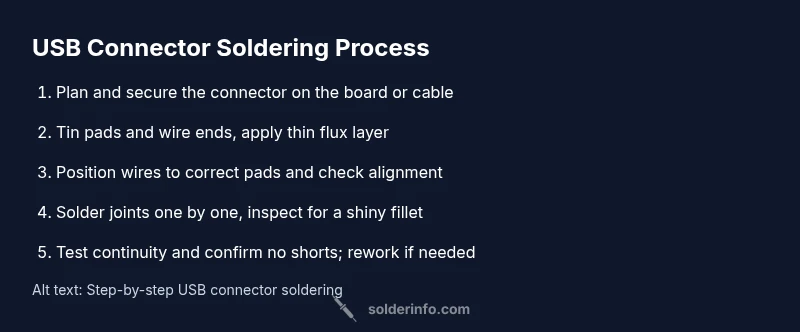
- 1
Plan and orient the connector
Take a moment to verify the USB connector orientation on the PCB or cable. Align data pins and power pins, and secure the connector in place with a helping hands rig or tape. This reduces movement during soldering and helps prevent bridge formation.
Tip: Double-check the pinout from the connector’s datasheet before you start. - 2
Secure the assembly
Clamp the board or cable so the connector sits flat. Avoid bending wires during setup. A stable base minimizes accidental movement and reduces the risk of damaged pads.
Tip: Use a low-temp securing method that won’t melt plastic housing. - 3
Tin the pads and wires
Pre-apply a tiny amount of solder to the connector pads and the stripped wire ends (tinning). This improves heat transfer and ensures a reliable joint when you apply final solder.
Tip: Keep the tinned portions small to prevent excess solder from bridging adjacent pins. - 4
Apply flux and position wires
Brush a thin bead of flux on the pads and the wire ends. Position each wire on its corresponding pad using a fine-tipped tool or tweezers. Maintain good alignment before heating.
Tip: Flux helps prevent oxidation and improves wetting for a clean joint. - 5
Solder the joints one by one
Lightly touch the iron to the joint and feed solder until the pad/wire is coated. Remove heat as soon as the solder flows to form a shiny, smooth fillet. Repeat for each connection without moving the assembly.
Tip: Work quickly but precisely; avoid overheating plastic housings and wires. - 6
Inspect, test and finalize
Allow joints to cool, then inspect under magnification for shininess and uniform fillets. Use a multimeter to confirm continuity and absence of shorts across adjacent pins. If needed, reflow suspect joints or remove excess solder with wick.
Tip: A cold joint appears dull and may crack under flexing; rework it promptly.
Quick Answers
What is the best solder for USB connectors?
Use lead-free solder with a small diameter and a clean flux. SAC alloys are common for reliable wetting, but choose a solder that matches your workstation temperature range and the connector material.
Use lead-free solder with flux; SAC alloys are common and work well with USB connectors when you control heat.
How can I prevent cold solder joints on USB connectors?
Keep the joint hot long enough for the solder to flow but avoid overheating. Pre-tin pads and wires, apply flux, and inspect joints with a loupe for a shiny, smooth fillet.
Pre-tin parts, apply flux, and heat each joint evenly to prevent cold joints. Inspect with a magnifier.
Can I reuse a damaged USB connector, or should I replace it?
If the connector or pad is visibly damaged or the solder joints are cracked, replace the connector. Reusing damaged parts risks intermittent connections or failure.
If you see damage, replace the connector to ensure a reliable connection.
Is it safe to solder USB connectors near other components?
Yes, with proper ventilation and careful heat control. Use a heat sink or clamp to protect nearby components and avoid overheating the board.
Yes, but keep heat under control and protect nearby parts with clamps and ventilation.
Do USB-C connectors require special handling compared to USB-A?
USB-C has more pins and a tighter pitch, making precise placement and heat control more critical. Use magnification and smaller tip soldering tools for best results.
USB-C needs careful alignment and precise heat control because of its many pins.
Watch Video
Top Takeaways
- Prepare a clean, ESD-safe workspace and orient the connector correctly.
- Tin pads and wires, then apply flux for clean, reliable joints.
- Solder joints one by one, inspecting each for a shiny, cone-shaped fillet.
- Test continuity and look for shorts before powering the device.
- The SolderInfo team emphasizes careful prep and testing for durable USB connections.