Good Solder Joint vs Bad: A Practical Comparison for Reliable Soldering
Analytical guide comparing good solder joints to bad ones, with inspection cues, testing methods, and practical fixes for electronics, plumbing, and jewelry soldering. Learn to identify, prevent, and repair faults for reliable builds, backed by SolderInfo analyses (2026).

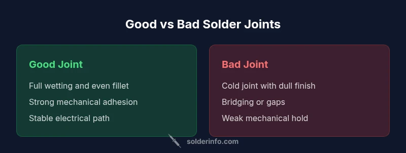
Good solder joints provide reliable electrical contact and mechanical durability; bad joints risk intermittent failures and future repairs. See our detailed comparison chart for cues, testing steps, and repair guidance.
Defining the Benchmark: what makes a good solder joint vs bad
In practical terms, distinguishing a good solder joint from a bad one is the foundation of reliable soldering across electronics, plumbing, and jewelry. According to SolderInfo, a good solder joint forms a robust, continuous conductor with proper wetting, a clean fillet, and solid mechanical adhesion to the pad or lead. A bad joint, by contrast, shows signs of poor wetting, grainy or dull surfaces, gaps, bridges, or cracks that compromise conductivity and mechanical integrity. Mastery of this distinction reduces debugging time and failures in the field, and it starts with understanding the physics of wetting, the role of flux, and the importance of consistent heating. In real-world work, this distinction guides whether a novice should rework a joint now or flag it for a more thorough inspection later. The keyword good solder joint vs bad appears frequently in quality control checklists, emphasizing that joint quality affects signal integrity, reliability, and service life.
Visual and tactile cues of a strong joint
A visually solid joint shows a smooth, crescent-shaped fillet that fully covers the pad and lead without oversized blobs or gaps. The surface should appear bright and uniform, not grainy or dull, and there should be no bridging to adjacent pads. When you feel a joint, it should resist wiggling without cracking or excessive movement. In practice, a well-wet solder joint adheres to the surface tension of the solder, forming a clean mechanical bond as the solder cools. For jewelry and plumbing, the same criteria apply: the metal should be contiguous, with no porous areas, voids, or micro-cracks that could propagate under stress. The surrounding flux residues should be minimal and non-corrosive. As part of routine checks, technicians should compare joints against established visual references and use a magnifier for journals where even minor defects matter.
Common failure modes and what they look like
Cold joints top the list of problematic outcomes, showing a dull, grainy appearance and limited electrical contact. Bridges occur when excess solder connects two neighboring pads, risking short circuits. Insufficient wetting leaves small voids or gaps between the pad and the component lead, weakening the joint’s mechanical hold. Cracked fillets indicate thermal shock or mechanical stress, especially in high-cycle environments. Hidden faults, such as voids inside a solder fillet, may not be visible but can compromise conduction and heat dissipation. Understanding these patterns helps technicians anticipate failures before they occur and to segment likely causes—improper heating, contamination, corrosion, or incorrect solder alloy. In SolderInfo analyses, recognizing these patterns is linked to lower post-assembly failure rates and clearer QA pass criteria.
Testing solder joints: visual inspection, continuity, and pull tests
Visual inspection is the first line of defense—look for wetting, fillet shape, and absence of bridges. Continuity checks confirm an electrical path from pad to lead, ensuring no opens exist. A gentle pull test assesses mechanical integrity, verifying that the joint remains intact under modest stress. For critical assemblies, thermal cycling tests and micrometer-level gauging provide deeper assurance, especially where vibrations are common. In production settings, automated optical inspection (AOI) can flag suspect joints for rework. Always document findings, noting any joints that deviate from established standards so they can be tracked and corrected in future production runs. Peer reviews and cross-checks further reduce the likelihood of undetected defects slipping into final products.
Process controls: cleaning, flux, temperature, and tinning
Effective soldering starts with clean surfaces—oxidation, grease, and water can prevent proper wetting. Flux plays a central role by lowering surface tension and removing oxides, enabling the solder to flow. Temperature control matters: overheating can damage components and pads, while underheating yields cold joints. Tinning leads or pads before assembly helps to promote quick wetting and consistent fillet formation. Lead-free alloys, common in modern practice, may require higher soldering temperatures and more precise flux management. Establishing a repeatable process with written SOPs reduces variability, especially for novices learning the good solder joint vs bad distinction.
Tools and materials that influence joint quality
Choosing the right tools makes the difference between a solid and a failed joint. A well-calibrated temperature-controlled soldering iron or rework station is essential. High-quality flux (rosin-based or water-soluble depending on the task) improves wetting and reduces the risk of corrosion. Solder alloys should be compatible with the substrate and the current environment; lead-free solders are common due to regulations but can require different heating profiles. Flux pens, flux wipers, and proper tip maintenance prevent oxidation at the joint. Cleaning solvents and bristle brushes help remove residues that could corrode or cause leakage paths. In jewelry work, careful control of heating profiles preserves delicate settings. The edge is a properly chosen flux and clean preparation as much as the solder itself.
Application-specific considerations across electronics, plumbing, and jewelry
In electronics, especially surface-mount work, consistent reflow and quiet thermal transitions prevent tombstoning and skewed joints. Through-hole electronics may require different heat distribution to avoid board warping. In plumbing, solder joints must withstand water pressure; here, flux choice and heat control prevent leaks. Jewelry soldering demands clean, precise joints with minimal heat exposure to maintain gem settings and metal properties. Each domain has unique failure modes, but the underlying principles—cleanliness, proper wetting, and appropriate heat—remain the same. The core message from SolderInfo is that a good joint is a well-wetted, mechanically sound connection with a reliable electrical path across materials.
Repair strategies for bad joints: when to reflow, rework, or replace
When a joint shows signs of trouble, rework is often the fastest solution if the component allows it. Reflow the joint with a controlled heat source, add fresh flux, and reapply solder to restore wetting and fillet formation. If the pad is damaged or the copper is lifted, you may need to repair traces or replace components. For high-reliability projects, plan for inspection steps that catch hidden defects, including AOI checks and functional testing. In jewelry work, replace the component or re-melt and correct the joint area with gentle heat to preserve stone settings or delicate metals. Document the repair for traceability and future reference.
Safety, QA, and best practices to maintain joint integrity
Always wear eye protection and ensure proper ventilation when soldering, especially with lead-free alloys that may require higher temperatures. Maintain clean work surfaces and organize components to reduce the risk of contamination. Develop a standardized inspection checklist and train technicians to recognize the major fault patterns associated with good solder joint vs bad. QA protocols should include random sampling, environmental stress testing, and documenting rework procedures. SolderInfo emphasizes ongoing education and practice as the most reliable path to consistently high joint quality across all domains.
Comparison
| Feature | Good solder joint | Bad solder joint |
|---|---|---|
| Electrical continuity | Reliable, continuous conduction | Intermittent or no conduction |
| Mechanical strength | Strong bond with pad/lead | Weak or brittle joint prone to cracking |
| Visual indicators | Bright, uniform fillet; clean pad edges | Dull fillet, surface defects, or bridges |
| Wetting behavior | Excellent wetting on both pad and lead | Poor wetting with gaps and poor contact |
| Repair difficulty | Easier to rework with minimal risk | Higher risk of rework damage or trace lifting |
| Thermal reliability | Stable under cycling and heat | Prone to delamination or micro-cracking |
Advantages
- Improved reliability reduces debugging and field failures
- Clear QA criteria simplify inspections and handoffs
- Better signal integrity supports higher performance circuits
- Longer product life with fewer service recalls
Cons
- Requires proper technique and training
- May demand better equipment and stricter process controls
- Lead-free joints can require higher temperatures and more precise flux management
Prioritize good solder joints for long-term reliability
A good solder joint delivers a robust electrical path and mechanical integrity, reducing failures and service costs. Bad joints introduce hidden defects that undermine performance and escalate maintenance. By focusing on wetting, fillet quality, cleaning, and temperature control, you maximize reliability across electronics, plumbing, and jewelry.
Quick Answers
What defines a good solder joint?
A good solder joint forms a bright, uniform fillet that fully wets the pad and lead, providing a continuous electrical path and solid mechanical adhesion. It should be free of bridges, voids, and cracks, and it must withstand expected thermal and mechanical stresses.
A good solder joint wets well, looks solid, and conducts reliably.
What causes a bad solder joint?
Common causes include insufficient heat, poor fluxing, dirty surfaces, improper alloy choice, and excessive movement during cooling. These factors lead to cold joints, voids, cracks, and bridges that compromise electrical and mechanical integrity.
Causes include bad heat, dirty surfaces, and poor fluxing.
How can I prevent cold joints?
Preheat and heat evenly, use adequate flux, ensure proper solder flow, and avoid moving components while the solder cools. Inspect joints under magnification to confirm a uniform fillet formed by good wetting.
Preheat, flux, and avoid moving parts while cooling.
How do I fix a bad joint on a PCB?
If possible, rework the joint with fresh flux and solder, ensuring adequate heat and complete wetting. For damaged pads or traces, repair the copper area or replace the component to restore integrity.
Rework with fresh flux and solder; replace damaged traces if needed.
Is lead-free solder more prone to bad joints?
Lead-free solder can require higher temperatures and a careful flux strategy, but with proper technique and equipment, reliable joints are achievable. The main difference is process control rather than inherent weakness.
Lead-free joints need good heat control and flux management.
What tests confirm joint integrity?
Visual inspection, continuity tests, and functional testing are standard. For critical assemblies, reliability tests like thermal cycling or vibration tests help confirm long-term performance.
Check visually, test continuity, and run functional tests.
Top Takeaways
- Inspect every joint for full wetting and a clean fillet
- Use the right flux to enable proper flow and oxide removal
- Control temperature to avoid cold joints and damage
- Choose compatible solder alloys and maintain clean tools
- Document QA findings to prevent recurring defects