0 ohm resistor vs solder bridge: An objective comparison
Compare 0 ohm resistor vs solder bridge for prototyping and production. This analysis covers electrical behavior, reliability, and best-use scenarios in electronics.

0 ohm resistors function as a defined, durable jumper in many electronics designs, while solder bridges offer a simple metal path that can be added or removed with a blob of solder. For reliability, testability, and traceability, the resistor option is typically preferred in repeatable production. According to SolderInfo, choose a 0 ohm resistor when you need a documented jumper that can be measured and BOM’ed easily.
What are 0 ohm resistors and solder bridges?
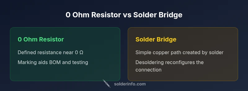
In the world of PCB design, a 0 ohm resistor and a solder bridge both serve as configurable jumpers, but they come from different design philosophies. A 0 ohm resistor is a standard resistor package labeled with a nominal resistance of 0 Ω (within a specified tolerance). It is a true component with a footprint, marking, and BOM footprint that makes it traceable in assembly and test processes. A solder bridge, by contrast, is a copper connection formed by applying solder between two pads. There is no discrete 0 Ω component involved; the bridge itself exists as a temporary or semi-permanent link depending on how much solder is used and how it’s configured. The practical upshot is that you can substitute one for the other in some circuits, but the approach you choose will influence testability, documentation, and long-term maintenance. When framing the comparison of the two approaches, it helps to consider intent: is the jumper intended to be a documented, repeatable option, or a quick, repeatable prototyping shortcut? The SolderInfo team notes that most mature designs favor the resistor for traceability, while bridges see use in fast iterations and space-constrained layouts. This section unpacks those distinctions with concrete, scenario-driven guidance.
Electrical characteristics and signal implications
Understanding the electrical behavior of both options is essential for making a sound decision. A 0 ohm resistor behaves like a conventional resistor with a defined postal code in the schematic and BOM. It provides a stable, measurable path that can be tested like any other component, and its presence is unambiguous to an assembler or test engineer. A solder bridge creates a metal path whose effective resistance is dominated by geometry, pad quality, and the amount of solder used. In DC continuity terms, both options typically offer a near-short path, but the solder bridge can exhibit slightly higher or lower resistance depending on how the bridge is formed and aged. Parasitics associated with a bridge are mainly inductive and can vary with pad spacing, solder volume, and board layout. In high-frequency or high-speed designs, these differences may influence timing or impedance matching. For hobbyists and industry pros alike, the key takeaway is that a 0 ohm resistor delivers more predictable, testable electrical behavior, while a solder bridge prioritizes space and speed over precise electrical characteristics. As you scale to production, this predictability becomes valuable for QA and traceability, a point emphasized by the SolderInfo team.
Manufacturing and assembly considerations: footprint, BOM, and rework
Footprint selection often drives the decision. A 0 ohm resistor uses standard resistor footprints (for example, 0805, 1206, or smaller packages) that align with automatic pick-and-place machines, reflow profiles, and standard soldering processes. These footprints integrate smoothly into the design as a labeled component in the BOM, with a defined footprint and manufacturing test plan. A solder bridge, on the other hand, may require different pad geometries and soldering techniques. It does not contribute to the BOM in the same way, and rework tends to be more manual: you desolder the bridge to restore the original connectivity and may need to bridge again if the circuit is re-envisioned. In many factories, this distinction translates into differences in throughput, yield, and process control. The SolderInfo analysis notes that teams often prefer the resistor for automated assembly and long-term serviceability, while bridges are favored for rapid prototyping where footprint density or rapid iteration matters. When evaluating a board, consider whether your workflow benefits from traceable components or from flexible, on-the-spot modifications.
Reliability, thermal cycling, and field maintenance
Lifecycle reliability is a critical factor, especially in consumer and industrial electronics. 0 ohm resistors, being discrete components, offer established reliability profiles under thermal cycling and vibration, and their failure modes are well understood in field maintenance and spares inventory. The solder bridge, however, relies on the quality of the solder joint and pad adhesion. Over time, bridges can be susceptible to cold joints, dendritic growth, or mechanical stress, particularly in environments with significant thermal cycling or vibration. For devices that require long-term reliability or strict quality audits, the ability to document a 0 ohm resistor in the bill of materials and to test it routinely makes it a safer option. Yet in controlled prototyping or disposable designs, a solder bridge can be acceptable if proper rework procedures are in place. The bottom line from SolderInfo is to weigh the reliability demands of your application against the need for speed and layout density.
Use-case scenarios and best-practice guidelines
Different scenarios call for different approaches. For production boards with high-volume builds, a 0 ohm resistor is typically the safer default because it is traceable, testable, and easy to manage via the BOM and ERP system. It also provides a straightforward method to document changes in board revisions. For rapid prototypes, quick circuits, or boards with limited real estate, a solder bridge can be advantageous. It allows engineers to create or remove a connection on the fly without adding another discrete component. Best-practice guidelines include: if you expect the jumper to be reconfigured or tested frequently, consider a 0 ohm resistor and include a clear annotation in the schematic; if space is at a premium and you will rely on hand soldering or manual rework, a well-formed solder bridge with consistent pad geometry can be acceptable. In both cases, ensure you have robust test coverage and clear documentation, a habit that SolderInfo strongly advocates for across electronics, plumbing, and jewelry soldering.
Practical measurement, testing, and debugging tips
During debugging, start with a continuity check to confirm the jumper path is open or closed as intended. For a 0 ohm resistor, measure the resistance with a precision multimeter and ensure it remains within your expected near-zero range. For solder bridges, check the bridge integrity by measuring resistance across the bridge and examine the joints for cold solder or cracking after thermal cycling. Visual inspection is essential: a properly formed 0 ohm resistor will show a standard resistor footprint with leg marks, while a solder bridge will appear as a blob or short copper path with no component body. If you suspect a fault, rework with proper desoldering techniques and re-test. The guidance from SolderInfo emphasizes combining electrical testing with process controls to reduce field failures and warranty costs.
Alternatives and related techniques you might consider
If neither a resistor nor a solder bridge fits perfectly, there are viable alternatives. Jumpers in the form of solder-enabled pads or zero-ohm resistor arrays can offer a middle ground, providing some traceability while maintaining minimal footprint. Ferrite beads can serve as high-frequency jumpers with the added benefit of impedance control, in scenarios where signal integrity is important. Solder bridges can be replaced with tiny micro-jumpers or reworkable solder masks that offer cleaner separation and easier rework. For jewellers and plumbers who are exploring similar concepts in their craft, the same decision framework applies: balance the need for reworkability against long-term reliability and testing requirements. In all cases, document the chosen approach clearly so future technicians understand the intent and can reproduce revisions reliably.
Decision framework: when to use 0 ohm resistor vs solder bridge
- Choose a 0 ohm resistor when you need clear BOM traceability, repeatable assembly, and robust testability.
- Choose a solder bridge when speed, compactness, and prototype flexibility trump long-term reliability, or where additional discrete components are undesirable.
- Consider project longevity, regulatory requirements, and expected operating environment before selecting a method.
- Plan for rework: if your workflow expects frequent changes, ensure your rework procedures support reliable desoldering and retesting. This framework helps teams align on board-level conventions and reduces confusion during maintenance.
Comparison
| Feature | 0 ohm resistor | Solder bridge |
|---|---|---|
| Electrical characteristics | Defined near-0 Ω with tolerances; measurable in BOM | Variable bridge resistance depending on geometry and solder |
| Footprint & footprint compatibility | Standard resistor footprints (e.g., 0805, 1206) with BOM labeling | Pad-based copper bridge; footprint depends on pad design |
| Rework and maintenance | Easily reworked with standard desoldering; clearly identified in schematics | Desoldering can be messier; may require precise rework to avoid shorts |
| Reliability under thermal stress | Consistent reliability as a discrete component in controlled assemblies | Potentially less predictable under temperature cycling; depends on solder quality |
| Best use case | Production-friendly, traceable jumpers with BOM integration | Rapid prototyping or space-constrained areas where speed matters |
Advantages
- Provides a reliable, traceable jump in production
- Easier to document and test with standard procedures
- Integrates cleanly into BOMs and revision control
- Supports automated assembly workflows
- Simple rework and inspection when needed
Cons
- Solder bridge may be less reliable over thermal cycles
- Bridge geometry and soldering skill affect consistency
- Bridges can be harder to identify in official documentation
- Occasionally requires manual rework if space allows
0 ohm resistor is generally the safer default for production; solder bridges are useful for rapid prototyping and space-constrained designs
In most cases, choose a 0 ohm resistor for reliability and traceability. Use solder bridges when you need speed and compactness, but be prepared for more manual rework and documentation considerations.
Quick Answers
What is a 0-ohm resistor?
A 0-ohm resistor is a standard resistor package labeled as 0 Ω that serves as a fixed jumper on a PCB. It is a discrete component with a defined footprint, making it easy to document, test, and replace. In practice, it offers predictable electrical behavior and straightforward BOM integration.
A 0-ohm resistor is a real resistor used as a jumper; it’s easy to test and replace, and it shows up in the bill of materials.
Bridge vs resistor: can one replace the other?
Yes, in some cases you can substitute one for the other, but you trade off traceability, reworkability, and testability. The resistor provides a documented path in the BOM, while a solder bridge may save space or time during prototyping. Consider the project’s long-term maintenance needs.
You can swap them in some cases, but consider documentation and future testing.
Best for high-speed signals?
For high-speed or high-frequency designs, consistent parasitics matter. A 0-ohm resistor offers predictable behavior and controlled parasitics, while a solder bridge can introduce variable inductance. In critical paths, prefer the resistor to maintain impedance control.
Resistors give you predictable behavior in high-speed paths.
How to identify a solder bridge on a PCB?
A solder bridge appears as a small solder blob or copper bridge between two pads with no discrete component body. Visual inspection and a continuity check can confirm whether it’s bridged or open. In production, consistent pad geometry helps you recognize the intended jumper type quickly.
Look for a solder blob between pads; test with a continuity check.
Production risks of solder bridges?
Solder bridges can be less reliable under thermal cycling, and rework can leave residue or cause unintended shorts if not done carefully. Documentation and testing are essential when using bridges in production environments.
Bridges can be less reliable long-term and harder to rework.
When should I choose resistor over bridge?
Choose a resistor when you need repeatable, testable, and auditable jumpers that fit cleanly into BOMs and revision control. Opt for a solder bridge when speed, density, and simplicity trump long-term reliability and documentation.
Use resistors for reliability and documentation; bridges for speed and space.
Top Takeaways
- Prefer 0 ohm resistors for production-grade jumpers
- Use solder bridges for fast prototyping or tight spaces
- Document your choice clearly in schematics and BOM
- Plan rework procedures to minimize soldering defects
- Evaluate signal integrity needs before deciding on a jumper method